Arduino Projects
Water level Monitoring With GSM
Introduction
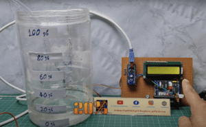
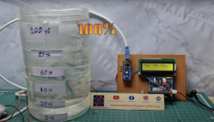
- Water is a precious resource, and monitoring the water level in tanks is crucial for efficient utilization and conservation. In this article, we will explore how to build a water tank level monitoring system using Arduino, which allows you to remotely monitor the water level and take necessary actions to ensure a sufficient supply. By utilizing Arduino’s flexibility and various sensors, this system provides an effective and cost-efficient solution for monitoring water levels.
- The Need for Water Tank Level Monitoring Water tanks is commonly used in residential, commercial, and industrial settings to store water for various purposes. However, without proper monitoring, it becomes challenging to determine the available water quantity accurately. This can lead to inefficient water usage, potential water shortages, and even damage to the pumping systems. A water tank level monitoring system addresses these concerns by providing real-time information about the water level, enabling users to make informed decisions.
- Building an Arduino-Based Water Tank Level Monitoring System An Arduino-based water tank level monitoring system offers an affordable and versatile solution for monitoring water levels. The Arduino board serves as the brain of the system, interfacing with sensors to measure the water level and display the information on an LCD display. Let’s explore the components and steps involved in building such a system.
Components Needed
- Arduino board (e.g., Arduino Nano)
- GSM module (e.g., SIM900 or SIM900)
- Multiple Wire (e.g., Copper Wire)
- Power supply (e.g., battery or AC adapter)
- SIM card with an active mobile number
Arduino Nano
- The Arduino Nano is powered by the ATmega328P microcontroller chip, which is the same microcontroller used in the Arduino Uno board. The ATmega328P operates at a clock speed of 16 MHz and has 32KB of flash memory, 2KB of SRAM, and 1KB of EEPROM.

- The Nano is significantly smaller compared to other Arduino boards, measuring approximately 45mm x 18mm. It is designed in a compact DIP (Dual Inline Package) format, making it suitable for projects with space constraints or when a smaller form factor is required.
- The Arduino Nano provides a total of 14 digital I/O pins, of which 6 can be used for PWM (Pulse Width Modulation) output. It also offers 8 analog input pins, each of which can provide a 10-bit resolution. These pins allow you to interface with various sensors, actuators, and other electronic components.
- The Nano has a built-in USB interface for programming and serial communication with a computer. It uses a mini USB connector for connecting to a computer. Additionally, it features a dedicated ICSP (In-Circuit Serial Programming) header for advanced programming and debugging.
16×2 LCD Display
- The 16×2 LCD display is rectangular in shape and typically measures around 80mm x 36mm. It usually consists of a backlit LCD screen, control circuitry, and a connection interface.

- The display has two rows, with each row capable of displaying up to 16 characters. The characters can be letters (both uppercase and lowercase), numbers, punctuation marks, symbols, and special characters.
- Many 16×2 LCD displays feature a built-in backlight, usually in the form of white or blue LEDs, to improve visibility in low-light conditions. The backlight can be controlled separately from the characters, allowing you to turn it on or off as needed.
- The LCD display module often includes an integrated controller, such as the commonly used HD44780 controller. The controller simplifies the interface with external devices by handling the low-level operations of displaying characters, managing the cursor position, and interpreting commands.
- The 16×2 LCD display can typically store and display custom-defined characters. These characters are created by defining a specific pattern of pixels and can be used to display icons, logos, or other specialized symbols beyond the standard character set.
GSM SIM900 Module
- The SIM900 module operates on GSM networks, allowing devices to send and receive data, make voice calls, and send SMS messages. It supports various GSM frequencies and can be used globally, depending on the specific variant.
- The SIM900 module usually comes in the form of a small PCB with pins for connecting to external devices. It requires a power supply (typically 5V) and uses UART (Universal Asynchronous Receiver-Transmitter) communication for interfacing with microcontrollers or other devices. It has TX (Transmit) and RX (Receive) pins for serial communication and additional pins for control and status monitoring.
- The module includes a SIM card holder or connector for inserting a standard-sized SIM card. The SIM card provides the necessary identification and network credentials for the module to connect to the GSM network.
- The SIM900 module communicates with external devices using AT (Attention) commands. These commands are sent via the UART interface and allow the device to control various features of the module, such as establishing network connections, sending SMS messages, making calls, and managing network settings. AT commands are ASCII-based instructions that follow a specific syntax defined by the module’s manufacturer.
Circuit Diagram
Source Code
|
1 2 3 4 5 6 7 8 9 10 11 12 13 14 15 16 17 18 19 20 21 22 23 24 25 26 27 28 29 30 31 32 33 34 35 36 37 38 39 40 41 42 43 44 45 46 47 48 49 50 51 52 53 54 55 56 57 58 59 60 61 62 63 64 65 66 67 68 69 70 71 72 73 74 75 76 77 78 79 80 81 82 83 84 85 86 87 88 89 90 91 92 93 94 95 96 97 98 99 100 101 102 103 104 105 106 107 108 109 110 111 112 113 114 115 116 117 118 119 120 121 122 123 124 125 126 127 128 129 130 131 132 133 134 135 136 137 138 139 140 141 142 143 |
#include <SoftwareSerial.h> SoftwareSerial mySerial(10, 11); #include <LiquidCrystal.h> int level1 = A5; int level2 = A4; int level3 = A3; int level4 = A2; int level5 = A1; int motor = 6; int a; int b; int c; int d; int e; int r; int m = 0; int z = 50; LiquidCrystal lcd(2, 3, 4, 5, 6, 7); void setup() { Serial.begin(9600); mySerial.begin(9600); pinMode(level1, INPUT); pinMode(level2, INPUT); pinMode(level3, INPUT); pinMode(level4, INPUT); pinMode(level5, INPUT); pinMode(motor, OUTPUT); lcd.begin(16, 2); } void loop() { r = digitalRead(motor); a = analogRead(level1); b = analogRead(level2); c = analogRead(level3); d = analogRead(level4); e = analogRead(level5); if (e > z && d > z && c > z && b > z && a > z) { { digitalWrite(motor, LOW); } lcd.clear(); lcd.setCursor(0, 0); lcd.print("Tank 100% FULL"); SendMessage(); mySerial.println("ATDxxxxxxxxxx;"); delay(100); mySerial.println("ATH"); } else { if (e < z && d > z && c > z && b > z && a > z) { lcd.clear(); lcd.setCursor(0, 0); lcd.print("Tank is 80% FULL"); SendMessage1(); } else { if (e < z && d < z && c > z && b > z && a > z) { lcd.clear(); lcd.setCursor(0, 0); lcd.print("Tank is 60% FULL"); SendMessage2(); } else { if (e < z && d < z && c < z && b > z && a > z) { lcd.clear(); lcd.setCursor(0, 0); lcd.print("Tank is 40% FULL"); SendMessage3(); } else if (e < z && d < z && c < z && b < z && a > z) { lcd.clear(); lcd.setCursor(0, 0); lcd.print("Tank is 20% FULL"); } else { if (e < z && d < z && c < z && b < z && a < z) { { digitalWrite(motor, HIGH); } } } } } } if (r == LOW) { lcd.setCursor(0, 0); lcd.print("Water Pump (OFF)"); } else { lcd.setCursor(0, 0); lcd.print("Water Pump (ON)"); } { delay(100); } } void SendMessage() { Serial.println("Tank 100% FULL"); mySerial.println("AT+CMGF=1"); delay(1000); mySerial.println("AT+CMGS=\"+91xxxxxxxxxx\"\r"); delay(1000); mySerial.println("Tank 100% FULL"); delay(100); mySerial.println((char)26); delay(1000); } void SendMessage1() { Serial.println("Tank is 80% FULLt"); mySerial.println("AT+CMGF=1"); delay(1000); mySerial.println("AT+CMGS=\"+91xxxxxxxxxx\"\r"); delay(1000); mySerial.println("Tank is 80% FULL "); delay(100); mySerial.println((char)26); delay(1000); } void SendMessage2() { Serial.println("Tank is 60% FULL"); mySerial.println("AT+CMGF=1"); delay(1000); mySerial.println("AT+CMGS=\"+91xxxxxxxxxx\"\r"); delay(1000); mySerial.println("Tank is 60% FULL"); delay(100); mySerial.println((char)26); delay(1000); } void SendMessage3() { Serial.println("Tank is 40% FULL"); mySerial.println("AT+CMGF=1"); delay(1000); mySerial.println("AT+CMGS=\"+91xxxxxxxxxx\"\r"); delay(1000); mySerial.println("Tank is 40% FULL"); delay(100); mySerial.println((char)26); delay(1000); } |
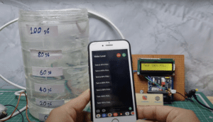
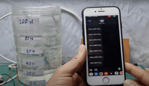
Projects Demo
Video Tutorial
GSM Related More Projects
Conclusion
A water tank level monitoring system built using Arduino and appropriate sensors offers a cost-effective and reliable solution for efficient water management. By accurately monitoring water levels, users can optimize water usage, prevent wastage, and ensure a consistent water supply. Implementing such a system contributes to sustainable water resource management and helps address the global water scarcity challenge we face today.


