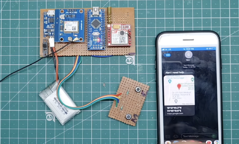
Introduction
GPS System is very commonly used in every field Like Vehicle Tracking, Human Tracking, Ship Tracking, And Bicycle Tracking System. In this tutorial, I will also soon the latitude and Longitude (GPS Coordinates) And Speed.
Small GPS Tracker uses component’s GPS Neo-6m, Sim800l, Arduino Nano,16×2 LCD Display, Push Button And Buzzer.
We Have Also built many types Of Vehicle Tracking Systems If You are Interested Plz Check Out
Bill Of Materials
S.N | Component's | Quantity | Link To Buy |
1 | Arduino Nano | 1 | |
2 | GPS Neo-6m Module | 1 | |
3 | GSM Sim800l Module | 1 | |
4 | 16x2 LCD Display | 1 | |
5 | I2C Module | 1 | |
6 | 10k Pot | 1 | |
7 | Push Button | 1 | |
8 | Buzzer | 1 | |
9 | Zero PCB | 1 | |
10 | 12V DC Supply | 1 |
All impotent Component Are Required To Make This Project
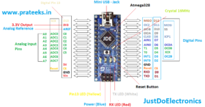
Arduino Nano
This one is the Pin Diagram of Arduino nono microcontroller
GSM Sim800l Module
LM2596 Step-Down Conveter
GPS Neo-6m Module
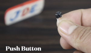
Push Button
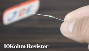
10K Resister
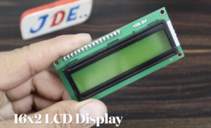
16×2 LCD Display
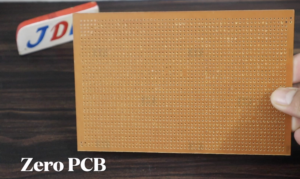
Zero PCB
Block Diagram
PCB Design
Circuit Diagram
These all are the circuit diagram for different connections We just flow the circuit diagram and Upload the proper code.
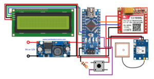
Circuit Diagram 1
In this circuit diagram, we just connect to the GPS Module, GSM Module, And Push Button Only. And I providing the 3.7v dc supply with the help of the LM2596 Step-Down Converter.
GSM Connection
- VCC – VCC
- Tx – 8
- Rx – 9
- GND – GND
GPS Connection
- VCC – VCC
- Tx – RX
- GND – GND
Push Button
- Pin Number – 3
Code
Before uploading just Change the number
|
1 |
char phone_no[] = "+91xxxxxxxxxx"; |
We Just Add the Library and change the Mobile Number then you upload the Code
|
1 2 3 4 5 6 7 8 9 10 11 12 13 14 15 16 17 18 19 20 21 22 23 24 25 26 27 28 29 30 31 32 33 34 35 36 37 38 39 40 41 42 |
//Prateek //www.justdoelectronics.com #include <TinyGPS.h> #include <SoftwareSerial.h> #include <Wire.h> SoftwareSerial Gsm(6, 7); char phone_no[] = "+91xxxxxxxxxx"; TinyGPS gps; int state; String textMessage; void setup() { Serial.begin(9600); Gsm.begin(9600); Serial.print("AT+CMGF=1\r"); delay(100); Serial.print("AT+CNMI=2,2,0,0,0\r"); delay(100); pinMode(10, INPUT); } void loop() { bool newData = false; unsigned long chars; unsigned short sentences, failed; for (unsigned long start = millis(); millis() - start < 1000;) { while (Serial.available()) { char c = Serial.read(); Serial.print(c); if (gps.encode(c)) newData = true; } } if (Gsm.available() > 0) { textMessage = Gsm.readString(); textMessage.toUpperCase(); delay(10); } //Prateek //www.justdoelectronics.com Serial.println(failed); } |
- When You Press the Push Button This Condition Will Happen
|
1 2 3 4 5 6 7 8 9 10 11 12 13 14 15 16 17 18 19 20 21 22 23 24 25 26 27 28 29 30 31 32 33 34 35 36 37 38 |
state = digitalRead(10); if (state == 0) //Prateek //www.justdoelectronics.com { float flat, flon; unsigned long age; gps.f_get_position(&flat, &flon, &age); Gsm.print("AT+CMGF=1\r"); delay(400); Gsm.print("AT+CMGS=\""); Gsm.print(phone_no); Gsm.println("\""); Gsm.println("Alert I need help............."); Gsm.print("http://maps.google.com/maps?q=loc:"); Gsm.print(flat == TinyGPS::GPS_INVALID_F_ANGLE ? 0.0 : flat, 6); Gsm.print(","); Gsm.print(flon == TinyGPS ::GPS_INVALID_F_ANGLE ? 0.0 : flon, 6); delay(200); Gsm.println((char)26); //Prateek //www.justdoelectronics.com delay(200); Gsm.println(); Serial.println("SMS Sent"); Serial.println("Call"); delay(20000); Gsm.println("ATD+91xxxxxxxxxx;"); delay(150000); Gsm.println("ATH"); delay(1000); } else { delay(10); } |
Circuit Diagram 2
Now, In this Circuit, I will Connect to the 16×2 LCD Display And when We press the push Button the LCD Will Display The “Push Button Is pressed” and also Display the GPS Coordinate.
LCD Connection
- GND – GND
- VCC – VCC
- SDA – A4
- SCL – A5
Code
Here You Put Your Mobile Number
|
1 |
char phone_no[] = "+91xxxxxxxxxx"; |
Then You Upload The Final Code
|
1 2 3 4 5 6 7 8 9 10 11 12 13 14 15 16 17 18 19 20 21 22 23 24 25 26 27 28 29 30 31 32 33 34 35 36 37 38 39 40 41 42 43 44 45 46 47 48 49 50 51 52 53 54 |
#include <TinyGPS.h> #include <SoftwareSerial.h> #include <Wire.h> #include <LiquidCrystal_I2C.h> LiquidCrystal_I2C lcd(0x27, 16, 2); SoftwareSerial Gsm(8, 9); char phone_no[] = "+91xxxxxxxxxx"; TinyGPS gps; int state; String textMessage; void setup() { Serial.begin(9600); Gsm.begin(9600); delay(2000); Serial.print("AT+CMGF=1r"); delay(100); Serial.print("AT+CNMI=2,2,0,0,0r"); delay(100); pinMode(3, INPUT_PULLUP); lcd.begin(); lcd.backlight(); lcd.clear(); lcd.print("Searching "); lcd.setCursor(0, 1); lcd.print("Network....... "); delay(3000); } void loop() { lcd.clear(); lcd.print("Woman Safity"); lcd.setCursor(0, 1); lcd.print("System...!!"); delay(100); bool newData = false; unsigned long chars; unsigned short sentences, failed; for (unsigned long start = millis(); millis() - start < 1000;) { while (Serial.available()) { char c = Serial.read(); Serial.print(c); if (gps.encode(c)) newData = true; } } if (Gsm.available() > 0) { textMessage = Gsm.readString(); textMessage.toUpperCase(); delay(10); } Serial.println(failed); if (chars == 0) Serial.println("** No characters received **"); } |
- When you press the Push Button
|
1 2 3 4 5 6 7 8 9 10 11 12 13 14 15 16 17 18 19 20 21 22 23 24 25 26 27 28 29 30 31 32 33 34 35 36 37 38 39 40 |
state = digitalRead(3); if (state == 1) { Serial.println("Button Press"); float flat, flon; unsigned long age; gps.f_get_position(&flat, &flon, &age); Gsm.print("AT+CMGF=1r"); delay(400); Gsm.print("AT+CMGS="""); Gsm.print(phone_no); Gsm.println(""); lcd.clear(); lcd.print("Sending location"); lcd.setCursor(0, 1); lcd.print("To Base...."); delay(3000); Gsm.println("Alert I need help "); Gsm.print("http://maps.google.com/maps?q=loc:"); Gsm.print("Latitude = "); Gsm.print(flat == TinyGPS::GPS_INVALID_F_ANGLE ? 0.0 : flat, 6); Gsm.print(" Longitude = "); Serial.print(","); Gsm.print(flon == TinyGPS::GPS_INVALID_F_ANGLE ? 0.0 : flon, 6); delay(200); Gsm.println((char)26); delay(200); Gsm.println(); delay(10000); lcd.clear(); lcd.print("location Sent"); delay(3000); } else { lcd.clear(); lcd.print("Welcome To"); lcd.setCursor(0, 1); lcd.print("Our System "); delay(10); } |
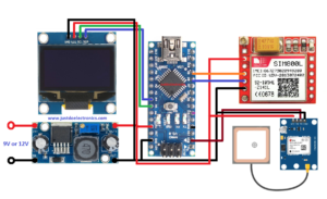
Circuit Diagram 3
In this circuit diagram, we just connected the OLED Display To the Arduino nano microcontroller the OLED displays the current location of the GPS.
OLED Display Connection
- GND – GND
- VCC – VCC
- SDA – A4
- SCL – A5
Code
Before uploading the Code Just Add 3 library
Now We Upload the Final Code
|
1 2 3 4 5 6 7 8 9 10 11 12 13 14 15 16 17 18 19 20 21 22 23 24 25 26 27 28 29 30 31 32 33 34 35 36 37 38 39 40 41 42 43 44 45 46 47 48 49 50 51 52 53 54 55 56 57 58 59 60 61 62 63 64 65 66 67 68 69 70 71 72 73 74 75 76 77 78 79 80 81 82 83 84 85 86 87 88 89 90 91 92 93 94 95 96 97 98 99 100 101 102 103 104 105 106 107 108 109 110 111 112 113 114 115 116 117 118 119 120 121 122 123 124 125 126 127 128 129 130 131 132 133 134 135 136 137 138 139 140 141 142 143 144 145 146 147 148 149 150 151 152 153 |
#include "Adafruit_FONA.h" #include <TinyGPS++.h> static const uint32_t GPSBaud = 9600; TinyGPSPlus gps; #define FONA_RX 9 #define FONA_TX 8 #define FONA_RST 10 char replybuffer[255]; String commands = ""; String YourArduinoData = ""; char latitude[15]; char longitude[15]; char fonaNotificationBuffer[64]; char smsBuffer[250]; #include <SoftwareSerial.h> SoftwareSerial fonaSS = SoftwareSerial(FONA_TX, FONA_RX); SoftwareSerial *fonaSerial = &fonaSS; #include <Wire.h> #include "SSD1306Ascii.h" #include "SSD1306AsciiWire.h" #define I2C_ADDRESS 0x3C #define RST_PIN -1 SSD1306AsciiWire oled; Adafruit_FONA fona = Adafruit_FONA(FONA_RST); uint8_t readline(char *buff, uint8_t maxbuff, uint16_t timeout = 0); void setup() { Serial.begin(GPSBaud); oled.begin(&Adafruit128x64, I2C_ADDRESS); oled.setFont(Callibri11_bold); Serial.println(F("FONA SMS caller ID test")); Serial.println(F("Initializing....(May take 3 seconds)")); pinMode(13, 1); fonaSerial->begin(4800); if (!fona.begin(*fonaSerial)) { oled.clear(); oled.print("Couldn't find SIM "); while (1) ; } Serial.println(F("FONA is OK")); fonaSerial->print("AT+CNMI=2,1\r\n"); Serial.println("FONA Ready"); oled.clear(); oled.println("SIM Ready"); } void loop() { getloc(); char *bufPtr = fonaNotificationBuffer; if (fona.available()) { int slot = 0; int charCount = 0; do { *bufPtr = fona.read(); oled.clear(); oled.print(fonaNotificationBuffer); delay(1); } while ((*bufPtr++ != '\n') && (fona.available()) && (++charCount < (sizeof(fonaNotificationBuffer) - 1))); *bufPtr = 0; if (1 == sscanf(fonaNotificationBuffer, "+CMTI: " FONA_PREF_SMS_STORAGE ",%d", &slot)) { Serial.print("slot: "); Serial.println(slot); char callerIDbuffer[32]; if (!fona.getSMSSender(slot, callerIDbuffer, 31)) { Serial.println("Didn't find SMS message in slot!"); } Serial.print(F("FROM: ")); Serial.println(callerIDbuffer); uint16_t smslen; if (fona.readSMS(slot, smsBuffer, 190, &smslen)) { Serial.println(smsBuffer); commands = smsBuffer; oled.clear(); oled.print(smsBuffer); Serial.println(commands); if (commands == "get loc") { digitalWrite(13, 1); YourArduinoData += ("https://www.google.com/maps/place/"); YourArduinoData.concat(latitude); YourArduinoData.concat(","); YourArduinoData.concat(longitude); Serial.println(YourArduinoData); char message[51]; YourArduinoData.toCharArray(message, 51); if (!fona.sendSMS(callerIDbuffer, message)) { Serial.println(F("Failed")); oled.clear(); oled.println("Failed"); } else { Serial.println(F("Sent!")); oled.clear(); oled.println("Location Sent!"); digitalWrite(13, 0); } } if ((fona.deleteSMS(slot)) || (fona.deleteSMS(1)) || (fona.deleteSMS(2)) || (fona.deleteSMS(3))) { } else { fona.print(F("AT+CMGD=?\r\n")); } } } } } void getloc() { if (Serial.available() > 0) if (gps.encode(Serial.read())) displayInfo(); if (millis() > 5000 && gps.charsProcessed() < 10) { Serial.println(F("No GPS detected: check wiring.")); oled.clear(); oled.println("No GPS detected: check wiring.."); while (true) ; } } void displayInfo() { oled.clear(); oled.print("Lati-"); oled.print(latitude); oled.println(",Long-"); oled.print(longitude); oled.println(" Date"); oled.print(gps.date.month()); oled.print("-"); oled.print(gps.date.day()); oled.print("-"); oled.print(gps.date.year()); oled.println("time"); oled.print(gps.time.hour()); oled.print(":"); oled.print(gps.date.day()); oled.print(":"); oled.print(gps.time.minute()); dtostrf(gps.location.lat(), 8, 7, latitude); dtostrf(gps.location.lng(), 8, 7, longitude); delay(50); } |
Demo Of Project
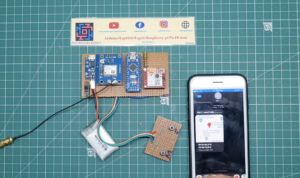
- When you press the push button after a few second the GSM send the text message with the proper GPS coordinates.
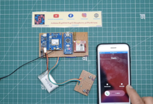
- Then you receive the call at the same number if you want to receive the call at a different number then change the code.
Video Tutorial






What a information of un-ambiguity and preserveness of valuable experience regarding unexpected feelings.
online store
http://staceylcrow.com