
Introduction
In this Tutorial, we will build a Smart shopping cart with an EM-18 RFID Module And Arduino. This project is easy to build because it requires only a few components. our system is just scanners in the mart all products have their own RFID tag, when you just scan the product name and price will display on an LCD Display.
You Can Check Also More Arduino Base Projects
Bill of Materials
S.N | Component's | Quanitity | Link To Buy |
1 | Arduino nano | 1 | |
2 | 16x2 LCD Display | 1 | |
3 | EM-18 Module | 1 | |
4 | Push Button | 1 | |
5 | Red LED | 1 | |
6 | Green LED | 1 | |
7 | Buzzer | 1 | |
8 | RFID Tag | 1 | |
9 | Zero PCB | 1 |
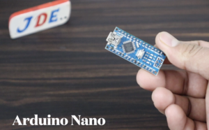
Arduino Nano
Here We used the Arduino nano controller and we showed the pin diagram of the Arduino nano microcontroller.
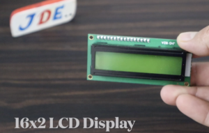
16×2 LCD Display
In this Project, we used the 16×2 LCD the team or the cost of the product that you purchase in a mart.
they are connected to the I2C protocol and are only four-pin connections.
- VCC – 5V
- GND – GND
- SDA – A4
- SCL – A5
If you did not use the I2C then You are required to connect a 4-pin connection I will provide all proper connections in this Article.
- Rs – 12
- Rw – GND
- E – 11
- D4 – 10
- D5 – 9
- D6 – 8
- D7 – 7

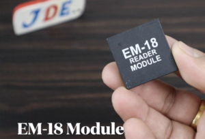
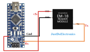
EM-18 RFID Module
- VCC – 5V
- GND – GND
- Tx – Rx
If you don’t know How You Find the Em-18 RFID Card Number then just Flow The Video
If you used the RC-522 RFID Module then follow the Article Smart Shopping Cart Using RC522 RFID
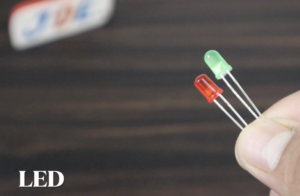
LED
we just connected the LED to Pin Numbers 7 And 8 or Pin Numbers 4 and 6
Buzzer
The Buzzer will be connected to PIN 6
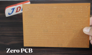
Zero PCB
We just soldering all the components in a Zero Pcb
Block Diagram
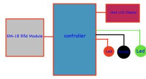
This one is The Block Diagram Of Our Project on the Input Side just connected to the EM-18 RFID Module and the output side Will be Connected to the 16×2 LCD Display, Buzzer, red LED, and green LED.
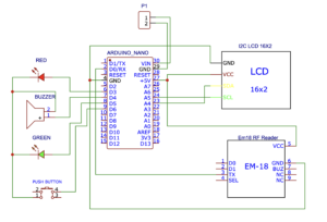
Circuit Diagram
With I2C Module-Based Circuit Diagram
Without I2C Module Based Circuit Diagram
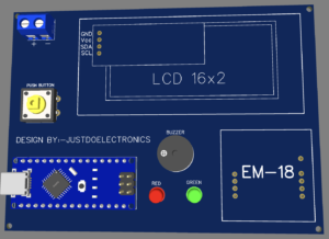
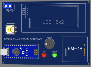
PCB Design
- we designed a PCB with the help of EasyEDA Software
- and in this circuit diagram, we used the 16×2 LCD Display With I2C Module.
Source Code
Before You Upload the Final code first find out the RFID Tag Number Using This Circuit Diagram & Code.
How to Find RFID Tag, Number Link
|
1 2 3 4 5 6 7 8 9 10 11 12 13 14 15 16 17 18 19 20 21 |
int count = 0; char card_no[12]; void setup() { Serial.begin(9600); } void loop() { if(Serial.available()) { count = 0; while(Serial.available() && count < 12) { card_no[count] = Serial.read(); count++; delay(5); } Serial.print(card_no); } } |
- Then Put the Code Here
|
1 |
if ((strncmp(input, "xxxxxxxxxxxx", 12) == 0) && (a == 1)) |
- Then You Uploading The Final Code with I2C
|
1 2 3 4 5 6 7 8 9 10 11 12 13 14 15 16 17 18 19 20 21 22 23 24 25 26 27 28 29 30 31 32 33 34 35 36 37 38 39 40 41 42 43 44 45 46 47 48 49 50 51 52 53 54 55 56 57 58 59 60 61 62 63 64 65 66 67 68 69 70 71 72 73 74 75 76 77 78 79 80 81 82 83 84 85 86 87 88 89 90 91 92 93 94 95 96 97 98 99 100 101 102 103 104 105 106 107 108 109 110 111 112 113 114 115 116 117 118 119 120 121 122 123 124 125 126 127 128 129 130 131 132 133 134 135 136 137 138 139 140 141 142 143 144 145 146 147 148 149 150 151 152 153 154 155 156 157 158 159 160 161 162 163 164 165 166 167 168 169 170 171 172 173 174 175 176 177 178 179 180 181 182 183 184 185 186 187 188 189 190 191 192 193 194 195 196 197 |
#include <Arduino.h> #include <Wire.h> #include <LiquidCrystal_I2C.h> LiquidCrystal_I2C lcd(0x27, 16, 2); char input[12]; int count = 0; int a; int p1 = 0, p2 = 0, p3 = 0, p4 = 0; int c1 = 0, c2 = 0, c3 = 0, c4 = 0; double total = 0; int count_prod = 0; void setup() { pinMode(A4, INPUT_PULLUP); pinMode(6, OUTPUT); pinMode(7, OUTPUT); pinMode(5, OUTPUT); lcd.init(); lcd.backlight(); lcd.clear(); Wire.begin(); Serial.begin(9600); lcd.setCursor(0, 0); lcd.print(" AUTOMATIC BILL"); delay(2000); lcd.setCursor(0, 1); lcd.print(" SHOPPING CART "); delay(2000); lcd.clear(); lcd.setCursor(0, 0); lcd.print("Plz Add iTem"); } void loop() { count = 0; while (Serial.available() && count < 12) { input[count] = Serial.read(); count++; delay(5); } int a = digitalRead(A4); if ((strncmp(input, "xxxxxxxxxxxx", 12) == 0) && (a == 1)) { lcd.setCursor(0, 0); lcd.print("Rice Added "); lcd.setCursor(0, 1); lcd.print("Price :- 10.00 "); p1++; digitalWrite(6, HIGH); digitalWrite(7, HIGH); digitalWrite(5, LOW); delay(2000); total = total + 10.00; count_prod++; digitalWrite(7, LOW); digitalWrite(6, LOW); digitalWrite(5, HIGH); } else if ((strncmp(input, "xxxxxxxxxxxx", 12) == 0) && (a == 0)) { if (p1 > 0) { lcd.clear(); lcd.setCursor(0, 0); lcd.print("Rice Removed!!! "); digitalWrite(6, HIGH); digitalWrite(7, HIGH); digitalWrite(5, LOW); delay(2000); p1--; total = total - 10.00; count_prod--; lcd.clear(); digitalWrite(6, LOW); digitalWrite(7, LOW); digitalWrite(5, HIGH); lcd.clear(); lcd.setCursor(0, 0); lcd.print("Total Price :-"); lcd.setCursor(0, 1); lcd.print(total); } else { lcd.clear(); lcd.setCursor(0, 0); lcd.print("Not in cart!!! "); digitalWrite(7, HIGH); digitalWrite(6, HIGH); digitalWrite(5, HIGH); delay(2000); digitalWrite(7, LOW); digitalWrite(6, LOW); digitalWrite(5, LOW); lcd.clear(); } } if ((strncmp(input, "xxxxxxxxxxx", 12) == 0) && (a == 1)) { lcd.setCursor(0, 0); lcd.print("Coffee Added "); lcd.setCursor(0, 1); lcd.print("Price :- 20.00 "); p2++; digitalWrite(7, HIGH); digitalWrite(6, HIGH); digitalWrite(5, LOW); delay(2000); total = total + 20.00; count_prod++; digitalWrite(7, LOW); digitalWrite(6, LOW); digitalWrite(5, HIGH); } else if ((strncmp(input, "xxxxxxxxxxx", 12) == 0) && (a == 0)) { if (p2 > 0) { lcd.clear(); lcd.setCursor(0, 0); lcd.print("Coffee Removed!!! "); digitalWrite(7, HIGH); digitalWrite(6, HIGH); digitalWrite(5, LOW); delay(2000); p2--; total = total - 20.00; count_prod--; lcd.clear(); digitalWrite(7, LOW); digitalWrite(6, LOW); digitalWrite(5, HIGH); lcd.clear(); lcd.setCursor(0, 0); lcd.print("Total Price :-"); lcd.setCursor(0, 1); lcd.print(total); } else { lcd.clear(); lcd.setCursor(0, 0); lcd.print("Not in cart!!! "); digitalWrite(7, HIGH); digitalWrite(6, HIGH); digitalWrite(5, HIGH); delay(2000); digitalWrite(7, LOW); digitalWrite(6, LOW); digitalWrite(5, LOW); lcd.clear(); } } if ((strncmp(input, "xxxxxxxxxxx", 12) == 0) && (a == 1)) { lcd.setCursor(0, 0); lcd.print("Oil Added "); lcd.setCursor(0, 1); lcd.print("Price :- 25.00 "); p3++; digitalWrite(7, HIGH); digitalWrite(6, HIGH); digitalWrite(5, LOW); delay(2000); total = total + 25.00; count_prod++; digitalWrite(7, LOW); digitalWrite(6, LOW); digitalWrite(5, HIGH); } else if ((strncmp(input, "xxxxxxxxxxx", 12) == 0) && (a == 0)) { if (p3 > 0) { lcd.clear(); lcd.setCursor(0, 0); lcd.print("Oil Removed!!! "); digitalWrite(7, HIGH); digitalWrite(6, HIGH); digitalWrite(5, LOW); delay(2000); p3--; total = total - 25.00; count_prod--; lcd.clear(); digitalWrite(7, LOW); digitalWrite(6, LOW); digitalWrite(5, HIGH); lcd.clear(); lcd.setCursor(0, 0); lcd.print("Total Price :-"); lcd.setCursor(0, 1); lcd.print(total); } else { lcd.clear(); lcd.setCursor(0, 0); lcd.print("Not in cart!!! "); digitalWrite(7, HIGH); digitalWrite(6, HIGH); digitalWrite(5, HIGH); delay(2000); digitalWrite(7, LOW); digitalWrite(6, LOW); digitalWrite(5, LOW); lcd.clear(); } } } |
Demo Of Project
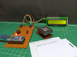
We just connected the USB cable to the Arduino nano microcontroller the LCD Will Display the Welcome Message.
Now we just scan the first item card and the LCD will display the item name and cost of the item.
Now we just scan the Second item card and the LCD will display the item name and cost of the item.
After a few seconds if we do not scan any card the LCD Will Display the total cost How many items do you purchase in a mart and how much cost you pay for the mart?
If you are interested in More Projects then Plz Check Out






Daii loper this your our project raa gandu I’ll give copyright, you ass hole meet yu in the court nee naa dengaaa, ladvee na malake, saisithe Bethene loperrrrrr
Sorry by mistake bro
Bt mistake bro
Poda kudhi
By mistake this comment ws posted on this unknown website
Umbu da umbu da mooci motta umbu da