Smart Shopping Cart Using EM-18 RFID And NodeMCU
Introduction
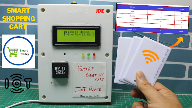
In this Tutorial, We make a smart shopping cart using RFID readers and RFID cards with NodeMCU.The cart will Display all information and the total value will be displayed on the webpage as well as on the LCD.
- we have faced a problem in shopping malls and markets. Because if you buy anything but when the time to pay bill is Wastes a lot of time in billing Process.
- That’s why we built a smart shopping cart with an automatic billing system. that not only reduces the waiting time but the payment process is easy for everyone.
- Here we used the RFID Cards and RFID Reader with nodeMCU(ESP8266) to build the smart shopping cart. and the cart information and total value will be displayed on the webpage as well on LCD Display.
- Each RFID Tag has a Different Product. and just put the Details in a code.RFID Reader is in the cart, which Reads the RFID tags and finds out the Product Details.
Bill of Materials
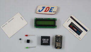
S.N. | Component | Quantity | Link To Buy |
1 | ESP8266 | 1 | |
2 | 20x4 LCD Display | 1 | |
3 | EM-18 RFID Module | 1 | |
4 | RFID Tag | 1 | |
5 | Red Led | 1 | |
6 | Green Led | 1 | |
7 | Buzzer | 1 | |
8 | Push Button | 1 |
Component
Here is all component of the project… We will give some Detail about each component.
ESP8266
NodeMCU is an IoT Module based on ESP8266 wifi Module. NodeMCU uses Lua Scripting language and is an open-source Internet of Things (IoT) platform. This module has CH340g USB to TTL IC.
Specification of Node-MCU IoT Module:-
- It is based on ESP8266 and integrates GPIO, PWM, IIC, 1-Wire and ADC in one board.
- Power your development in the fastest way by combining with NodeMCU Firmware!
- USB-TTL included plug&play
- 10 GPIO, every GPIO can be PWM, I2C, 1-wire
Features of Node-MCU IoT Module:-
- Open-source IoT Platform
- Easily Programmable
- Low Cost & Simple to Implement
- WI-FI enabled
EM-18 Reader Module
This EM-18 RFID Reader is a Tiny, simple-to-use RFID reader module. With a built-in antenna, the only holdup is the 2mm pin spacing. Power the module, hold up a card and get a serial string output containing the unique ID of the card. It has TTL output.
Specifications –
- Operating Voltage: 5V DC Supply
- Reading Distance: 6-10 cm.
- Read frequency: 125 kHz.
- EM4001 64–bit RFID tag compatible.
- 9600bps ASCII output.
- Current : <50 mA
- Operating Frequency: 125 kHz
- Read Distance: 5 cm
- Compatible Tags: 125KHz EM4100 Tags
Application –
- Smart Access Control System.
- Card-Based Entry System.
- Attendance System.
- Smart Trolly
LED
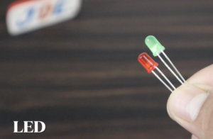
A Red light-emitting diode (LED) is a semiconductor light source. LEDs are used as indicator lamps in many devices and are increasingly used for other lighting. It looks like a Red led and it luminate Red light.
Features:-
- Choice of various viewing angles
- Reliable and robust
- The product itself will remain within RoHS compliant version Applications
Specifications:-
- Diameter : 3 mm
- Glow Color: Red, Green
- Forward voltage: 2.2 V to 2.4 V
- Peak Reverse Voltage: 5 volts
Buzzer
The active Buzzer Alarm Module for Arduino is an audio signalling device, which may be mechanical, electromechanical, or piezoelectric. Just like what you are viewing now, it is 3.3V-5V DC Electronic Part Active Buzzer Module.
Push Button
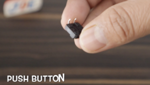
These are very small light duty SPST Single Pole Single push buttons that are NO Normally Open. Push buttons are only rated up to 50mA at 5V DC and are intended for low-voltage operations such as providing digital inputs to microcontrollers.
Circuit Diagram
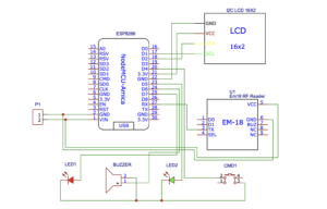
we will use EasyEDA Software to Design The Circuit Diagram And Proper PCB of the Project.
- We just connect the all component in the ESP8266 Microcontroller Pin. The 16×2 LCD Display Will be connected to the I2C Pine Numbers SCL-D1, SDA-D2, VCC-5v And GND-GND.
- The EM-18 Module Will Connect To The TX-RX Pin, VCC-5V And GND-GND.
- The Red Led Will be connected to Pin number D7, Green Led-D5, and Buzzer-D6 and The Push button Will be connected to Pin Numbr-D4.
Source Code
Here we will give the code Before You upload the code you just Edit the wifi SSID And Password And Then You Select the proper Board and Upload The Code.
|
1 2 3 4 5 6 7 8 9 10 11 12 13 14 15 16 17 18 19 20 21 22 23 |
#include<ESP8266WiFi.h> #include<WiFiClient.h> #include<ESP8266WebServer.h> #include<LiquidCrystal_I2C.h> #include<Wire.h> void printDetail(uint8_t type, int value); LiquidCrystal_I2C lcd(0x3f, 16, 2); const char* ssid = "justdo"; const char* password = "@12345"; ESP8266WebServer server(80); String page = ""; char input[12]; int count = 0; int a; int p1 = 0, p2 = 0, p3 = 0, p4 = 0; int c1 = 0, c2 = 0, c3 = 0, c4 = 0; double total = 0; int count_prod = 0; int led1 = D5; int led2 = D7; int buzzer = D6; |
Void Setup Function
|
1 2 3 4 5 6 7 8 9 10 11 12 13 14 15 16 17 18 19 20 21 22 23 24 25 26 27 28 29 30 31 32 33 34 35 36 37 38 39 40 41 42 43 44 45 46 47 48 49 50 51 52 53 |
void setup() { Serial.begin(115200); pinMode(D4, INPUT_PULLUP); pinMode(led1, OUTPUT); pinMode(led2, OUTPUT); pinMode(buzzer, OUTPUT); Serial.begin(9600); WiFi.begin(ssid, password); Wire.begin(D2, D1); lcd.begin(); lcd.backlight(); lcd.setCursor(0, 0); lcd.print("WELCOME TO"); lcd.setCursor(0, 1); lcd.print("SMART TROLLY"); delay(2000); lcd.clear(); while (WiFi.status() != WL_CONNECTED) { delay(500); lcd.setCursor(3, 0); lcd.print("WiFi Connecting... "); } Serial.print(WiFi.localIP()); lcd.setCursor(0, 0); lcd.print("WiFi Connected"); lcd.setCursor(0, 1); lcd.print(WiFi.localIP()); delay(2000); lcd.clear(); lcd.setCursor(0, 0); lcd.print(" PLZ SCAN ITEMS"); lcd.setCursor(0, 1); lcd.print(" TO CART"); server.on("/", []() { page = "<html><head><title>Smart Shopping Cart</title></head><style type=\"text/css\">"; page += "table{border-collapse: collapse;}th {background-color: #4444db ;color: white;}table,td {border: 4px solid black;font-size: x-large;"; page += "text-align:center;border-style: groove;border-color: rgb(255,0,0);}</style><body><center>"; page += "<h1>Welcome To Smart Cart Trolly</h1><br><br><table style=\"width: 1200px;height: 450px;\"><tr>"; page += "<th>ITEMS</th><th>QUANTITY</th><th>COST</th></tr><tr><td>Suger</td><td>" + String(p1) + "</td><td>" + String(c1) + "</td></tr>"; page += "<tr><td>Milk</td><td>" + String(p2) + "</td><td>" + String(c2) + "</td></tr><tr><td>Biscuits</td><td>" + String(p3) + "</td><td>" + String(c3) + "</td>"; page += "</tr><tr><td>Dairy Mlik</td><td>" + String(p4) + "</td><td>" + String(c4) + "</td></tr><tr><th>Grand Total</th><th>" + String(count_prod) + "</th><th>" + String(total) + "</th>"; page += "</tr></table><br><input type=\"button\" name=\"Pay Online Now\" value=\"Pay Online Now\" style=\"width: 200px;height: 50px\"></center></body></html>"; page += "<meta http-equiv=\"refresh\" content=\"2\">"; server.send(200, "text/html", page); }); server.begin(); } |
Void loop Function
|
1 2 3 4 5 6 7 8 9 10 11 12 13 14 15 16 17 18 19 20 21 22 23 24 25 26 27 28 29 30 31 32 33 34 35 36 37 38 39 40 41 42 43 44 45 46 47 48 49 50 51 52 53 54 55 56 57 58 59 60 61 62 63 64 65 66 67 68 69 70 71 72 73 74 |
void loop() { int a = digitalRead(D4); if (Serial.available()) { count = 0; while (Serial.available() && count < 12) { input[count] = Serial.read(); count++; delay(5); } if (count == 12) { if ((strncmp(input, "03007C4D2517", 12) == 0) && (a == 1)) { lcd.clear(); lcd.setCursor(0, 0); lcd.print("Suger Added"); lcd.setCursor(0, 1); lcd.print("Price(Rs):35.00"); p1++; digitalWrite(led1, HIGH); digitalWrite(buzzer, HIGH); delay(2000); total = total + 35.00; count_prod++; digitalWrite(led1, LOW); digitalWrite(buzzer, LOW); lcd.clear(); lcd.setCursor(0, 0); lcd.print("Total Price:-"); lcd.setCursor(0, 1); lcd.print(total); } else if ((strncmp(input, "03007C4D2517", 12) == 0) && (a == 0)) { if (p1 > 0) { lcd.clear(); lcd.setCursor(0, 0); lcd.print("Suger Removed"); digitalWrite(led2, HIGH); digitalWrite(buzzer, HIGH); delay(2000); p1--; total = total - 35.00; count_prod--; digitalWrite(led2, LOW); digitalWrite(buzzer, LOW); lcd.clear(); lcd.setCursor(0, 0); lcd.print("Total Price:-"); lcd.setCursor(0, 1); lcd.print(total); } else { lcd.clear(); lcd.setCursor(0, 0); lcd.print(" PLZ SCAN ITEMS"); lcd.setCursor(0, 1); lcd.print(" TO CART"); } } else { lcd.clear(); lcd.setCursor(0, 0); lcd.print(" PLZ SCAN ITEMS"); lcd.setCursor(0, 1); lcd.print(" TO CART"); } } else { lcd.clear(); lcd.setCursor(0, 0); lcd.print(" PLZ SCAN ITEMS"); lcd.setCursor(0, 1); lcd.print(" TO CART"); } } server.handleClient(); } |
More Project
- Smart Shopping Cart Using RFID & Arduino
- RC-522 RFID Interfacing With ARDUINO, ESP8266 & ESP32
- EM-18 RFID Interfacing With Arduino, ESP8266 & ESP32
Video

