Introduction
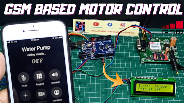
In This tutorial, we make a gsm-based smart motor controlling System. we controlling the water pump motor using the just given the one miscalled.
Agriculture is the biggest industry in India which serves food for more than a billion people every year. Producing many amounts of food is never an easy task, irrigation is one of the factors. Most of the agriculturist’s crop field is situated far from their residence, and just turning on the water pump costs huge for their transportation per year. This SMS-based GSM pump motor controller takes a baby step towards agricultural development, this may not be a revolutionary project but, it may bring delight among agriculturists.
we just need to call the water pump sim card number the gsm received the call and after 3 and 4-sec automated cuts, the call and the water pump motor will be ON and Feedback Message will come “Motor Is Trun ON” When you call again the GSM Received the call and after 3 and 4 Sec is Automatic.
Bill of Material
We Will use a few components in this project…
S.N | Component | Quantity | Link To Buy |
1 | Arduino Nano | 1 | |
2 | 16x2 LCD Dispaly | 1 | |
3 | SIM800l GSM Module | 1 | |
4 | 5V Relay Module | 1 | |
5 | Red Led | 1 | |
6 | Green Led | 1 | |
7 | DC Water Pump | 1 | |
8 | 12V Dc Power Supply | 1 |
Components
Arduino Nano
- Nano Version is the open-source smallest Embedded Development board based on Atmega328 SMD Package Microcontroller.
- It is a Surface mount Breadboard Friendly board integrated with Mini USB Port. DC Power Jack is not available on this Board, so power can be given through Mini USB Cable.
Specifications:-
- Microcontroller: Atmel ATmega328 SMD Package
- Operating Voltage (logic level): 5v DC
- Input Voltage: 7-12 v
- Input Voltage: 6-20 v
- Digital I/O Pins: 14 (of which 6 provide PWM output)
- Analog Input Pins: 8
16×2 LCD Display
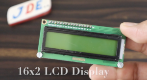
- This is a basic 16-character by 2 lines Alphanumeric display. Black text on Green background. Utilises the extremely common HD44780 parallel interface chipset. Interface code is freely available.
- You will need a Minimum of 6 general I/O pins to interface to this LCD screen. Includes LED backlight. Works in 4-bit and 8-bit Modes.
Features:-
- 16 Characters x 2 Lines
- Green Backlight
- HD44780 Equivalent LCD Controller/driver Built-In
- 4-bit or 8-bit MPU Interface
- Power Source Required DC 5v
GSM SIM800l
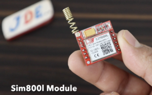
The SIM800L GSM module is a small device that communicates over the Global System for cellular network Communications. The module connects to a Mobile cellular network and transmits data, make voice calls, and sends text messages.
- Sim800L Module is a low-cost, low-form factor GSM module based on Simcoms SIM800L chipset.
- Sim800L module supports quad-band GSM and GPRS networks.
- The works in a frequency range of 850MHz to 1900MHz. It also works with AT commands.
- The GSM Module requires a power supply of around 3.7 to 4.2 volts.
- This breakout board is perfect for applications where size and cost is a constraints. Sim800l gsm module also supports quad-band, meaning it can work anywhere in the world.
Using this module you can:-
- Send Text Messages (SMS)
- Make or receive Phone calls
- Connect to the Internet via GPRS
- TCP/IP
5V Relay Module
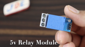
- This is 1 Channel 5V Relay Board Module we just control the relay in different microcontroller Like Arduino PIC AVR DSP ARM.
- The relay module is used to switching the output device.
Circuit Diagram
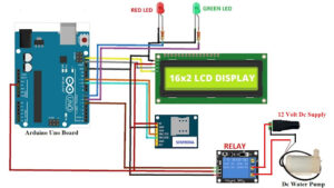
Now We connected all components with an Arduino nano microcontroller.
- The LCD Display will be connected to the I2C Module and it has only four connections SDA, SCL, VCC And GND.
- The SDA Pin is connected to the A4, SCL Pin-Connected To the A5,VCC is Connected to the 5V And GND Will be connected to the GND Pin.
- The GSM SIM800l Module is connected to the Pin Number D10 And D11. The Tx Pin is Connected to Pin Number D10 And The Rx Pin is Connected to Pin Number D11.
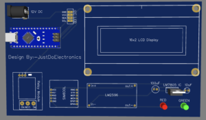
- we used the LM2596 Step Down converter because the GSM SIM800l Module required the 3.7V to 4.2 Volt to operate properly. we gave the 9V dc Supply and the LM2596 Convert the 3.7V Only.
- The RED And GREEN Led Will be connected to pin numbers D6 And D7 we used the 5V channel relay module and they will be connected to pin number D4.
- We will use EasyEDA Software to design the circuit Diagram.
- First We Created a new project then we add one by one all component.
Source Code
- we used the Arduino ide software to edit the code and then you select the proper Board and then upload the code
|
1 2 3 4 5 6 7 8 9 10 11 12 13 14 15 16 17 18 19 20 21 22 23 24 25 26 27 28 29 30 31 32 33 34 35 36 37 38 39 40 41 42 43 44 45 46 47 48 49 50 51 52 53 54 55 56 57 58 59 60 61 62 63 64 65 66 67 68 69 70 71 72 73 74 75 76 77 78 79 80 81 82 83 84 85 86 87 88 89 90 91 92 93 94 95 96 97 98 99 100 101 102 103 104 105 106 107 108 109 110 111 112 113 114 115 116 117 118 119 120 121 122 123 124 125 126 127 128 129 130 131 132 133 134 135 136 137 138 139 140 141 142 143 144 145 146 147 148 149 150 151 152 153 154 155 156 157 158 159 160 161 162 163 164 165 166 167 168 169 170 171 172 173 174 175 176 177 178 179 180 181 182 183 184 185 186 187 188 189 190 191 192 193 194 195 196 197 198 199 200 201 202 203 204 205 206 207 208 209 210 211 212 213 214 215 216 217 218 219 220 221 222 223 224 225 226 227 228 229 230 231 232 233 234 235 236 237 238 239 240 241 242 243 244 245 246 247 248 249 250 251 252 253 254 255 256 257 258 259 260 261 262 263 264 265 266 267 268 269 270 271 272 273 274 275 276 277 278 279 280 281 282 283 284 285 286 287 288 289 290 291 292 293 294 295 296 297 298 299 300 301 302 303 304 305 306 307 308 309 310 311 312 313 314 315 316 317 318 319 320 321 322 323 324 325 326 327 328 329 330 331 332 333 334 335 336 337 338 339 340 341 342 343 344 345 346 347 348 349 350 351 |
//Prateek //www.justdoelectronics.com #include <LiquidCrystal_I2C.h> #include <SoftwareSerial.h> #include <EEPROM.h> SoftwareSerial gsm(10, 11); // RX, TX LiquidCrystal_I2C lcd(0x27, 16, 2); int address = 0; int wr_call_add = 1; int f_address = 2; int eeprom_dead = 3; int wr_call_val = 0; int f_value = 70; int value = 0; int ring = 0; int i = 0; int var = 0; int eeprom_tst = 0; int eeprom_tst_ack = 0; int tst_var = 100; int wr_call_tst = 100; int eeprom_dead_val = 0; String number = ""; String string = ""; const int output = 5; const int red = 7; const int buzzer = 4; const int green = 6; boolean wait = true; boolean at_flag = 1; boolean net_flag = 1; void setup() { Serial.begin(9600); lcd.init(); lcd.backlight(); gsm.begin(9600); pinMode(output, OUTPUT); pinMode(red, OUTPUT); pinMode(buzzer, OUTPUT); pinMode(green, OUTPUT); if (EEPROM.read(f_address) != f_value) { EEPROM.write(f_address, f_value); EEPROM.write(address, value); EEPROM.write(wr_call_add, wr_call_val); eeprom_dead_val = 0; EEPROM.write(eeprom_dead, eeprom_dead_val); } if (EEPROM.read(eeprom_dead) == 1) { while (true) { lcd.clear(); lcd.setCursor(0, 0); lcd.print("EEPROM Error."); lcd.setCursor(0, 1); lcd.print("System Disabled."); delay(1500); lcd.clear(); lcd.setCursor(0, 0); lcd.print("Reload the code"); lcd.setCursor(0, 1); lcd.print("with new address"); delay(1500); } } if (EEPROM.read(address) == 0) { digitalWrite(output, LOW); digitalWrite(red, HIGH); digitalWrite(buzzer, LOW); delay(2000); digitalWrite(green, LOW); gsm_init(); lcd.clear(); if (EEPROM.read(wr_call_add) == 0) { lcd.setCursor(0, 0); lcd.print("Sending SMS"); lcd.setCursor(0, 1); lcd.print("Acknowledgement."); delay(1000); gsm.println("AT+CMGF=1"); delay(500); gsm.print("AT+CMGS="); gsm.print("\""); gsm.print(str); gsm.println("\""); delay(1000); gsm.println("Motor is OFF / System is Ready."); delay(100); gsm.println((char)26); } if (EEPROM.read(wr_call_add) == 1) { wr_call_val = 0; EEPROM.write(wr_call_add, wr_call_val); } } if (EEPROM.read(address) == 1) { eeprom_test(); output_begin(); } } void(* resetFunc) (void) = 0; void loop() { serialEvent(); if (ring == 1) { number = "+91xxxxxxxxxx"; var = string.indexOf("+CLIP: \""); if (var > 0) { number += string.substring(var + 8, var + 13 + 7); } if (number[0] == str[0] && number[1] == str[1] && number[2] == str[2] && number[3] == str[3] && number[4] == str[4] && number[5] == str[5] && number[6] == str[6] && number[7] == str[7] && number[8] == str[8] && number[9] == str[9] && number[10] == str[10] && number[11] == str[11]) { gsm.println("ATH"); lcd.clear(); lcd.setCursor(0, 0); lcd.print("Incomming call"); lcd.setCursor(0, 1); lcd.print("Number Verified."); delay(2000); if (EEPROM.read(address) == 0) { EEPROM.write(address, 1); } else if (EEPROM.read(address) == 1) { EEPROM.write(address, 0); } resetFunc(); } if (!(number[0] == str[0] && number[1] == str[1] && number[2] == str[2] && number[3] == str[3] && number[4] == str[4] && number[5] == str[5] && number[6] == str[6] && number[7] == str[7] && number[8] == str[8] && number[9] == str[9] && number[10] == str[10] && number[11] == str[11])) { gsm.println("ATH"); lcd.clear(); lcd.setCursor(0, 0); lcd.print("Unknown number"); lcd.setCursor(0, 1); lcd.print("Call Rejected."); wr_call_val = 1; EEPROM.write(wr_call_add, wr_call_val); delay(2000); resetFunc(); } } if (EEPROM.read(address) == 0) { serialEvent(); lcd.clear(); lcd.setCursor(0, 0); lcd.print("System Standby"); lcd.setCursor(0, 1); lcd.print("Status: OFF"); delay(1000); } else if (EEPROM.read(address) == 1) { lcd.setCursor(0, 0); lcd.print("STATUS: ON"); lcd.setCursor(0, 1); lcd.print("----------------"); } } void gsm_init() { lcd.print("System booting...."); lcd.setCursor(0, 1); lcd.print("initiating......"); delay(1500); lcd.clear(); lcd.setCursor(0, 0); lcd.print("Checking Module"); lcd.setCursor(0, 1); lcd.print("Connectivity...."); while (at_flag) { gsm.println("AT"); while (gsm.available() > 0) { if (gsm.find("OK")) at_flag = 0; } delay(1000); } lcd.clear(); lcd.setCursor(0, 0); lcd.print("Module"); lcd.setCursor(0, 1); lcd.print("Connection: OK"); delay(1500); eeprom_test(); lcd.clear(); lcd.setCursor(0, 0); lcd.print("System is Ready"); lcd.setCursor(0, 1); lcd.print("----------------"); delay(1500); } void serialEvent() { while (gsm.available()) { char read_char = gsm.read(); string += read_char; i++; if (string[i - 4] == 'R' && string[i - 3] == 'I' && string[i - 2] == 'N' && string[i - 1] == 'G' ) { ring = 1; } } } void output_begin() { digitalWrite(red, LOW); digitalWrite(buzzer, HIGH); delay(2000); digitalWrite(buzzer, LOW); digitalWrite(green, HIGH); if (EEPROM.read(wr_call_add) == 0) { lcd.clear(); lcd.setCursor(0, 0); lcd.print("Sending SMS"); lcd.setCursor(0, 1); lcd.print("Acknowledgement."); delay(1000); gsm.println("AT+CMGF=1"); delay(500); gsm.print("AT+CMGS="); gsm.print("\""); gsm.print(str); gsm.println("\""); delay(1000); gsm.println("Motor is ON."); delay(100); gsm.println((char)26); } if (EEPROM.read(wr_call_add) == 1) { wr_call_val = 0; EEPROM.write(wr_call_add, wr_call_val); } lcd.clear(); } void eeprom_test() { lcd.clear(); lcd.setCursor(0, 0); lcd.print("Testing EEPROM"); lcd.setCursor(0, 1); lcd.print("Memory."); delay(1500); eeprom_tst = EEPROM.read(address); eeprom_tst_ack = EEPROM.read(wr_call_add); EEPROM.write(address, tst_var); EEPROM.write(wr_call_add, wr_call_tst); if (EEPROM.read(address) == tst_var && EEPROM.read(wr_call_add) == wr_call_tst) { EEPROM.write(address, eeprom_tst); EEPROM.write(wr_call_add, eeprom_tst_ack); if (EEPROM.read(address) != eeprom_tst || EEPROM.read(wr_call_add) != eeprom_tst_ack) { digitalWrite(output, LOW); digitalWrite(red, HIGH); digitalWrite(buzzer, LOW); delay(2000); digitalWrite(green, LOW); eeprom_dead_val = 1; EEPROM.write(eeprom_dead, eeprom_dead_val); lcd.clear(); lcd.setCursor(0, 0); lcd.print("EEPROM Test is"); lcd.setCursor(0, 1); lcd.print("Unsuccessful."); delay(1500); } else if (EEPROM.read(address) == eeprom_tst && EEPROM.read(wr_call_add) == eeprom_tst_ack) { lcd.clear(); lcd.setCursor(0, 0); lcd.print("EEPROM Test is"); lcd.setCursor(0, 1); lcd.print("Successful."); delay(1500); } } else if (EEPROM.read(address) != tst_var || EEPROM.read(wr_call_add) != wr_call_tst) { digitalWrite(output, LOW); digitalWrite(red, HIGH); digitalWrite(buzzer, LOW); delay(2000); digitalWrite(green, LOW); eeprom_dead_val = 1; EEPROM.write(eeprom_dead, eeprom_dead_val); lcd.clear(); lcd.setCursor(0, 0); lcd.print("EEPROM Test is"); lcd.setCursor(0, 1); lcd.print("Unsuccessful."); delay(1500); } } void eeprom_sms() { lcd.clear(); lcd.setCursor(0, 0); lcd.print("Sending SMS"); lcd.setCursor(0, 1); lcd.print("Acknowledgement"); delay(1000); gsm.println("AT+CMGF=1"); delay(500); gsm.print("AT+CMGS="); gsm.print("\""); gsm.print(str); gsm.println("\""); delay(1000); gsm.println("EEPROM error. System disabled. Please reload the code with new address."); delay(100); gsm.println((char)26); { lcd.clear(); lcd.setCursor(0, 0); lcd.print("EEPROM Error."); lcd.setCursor(0, 1); lcd.print("System Disabled."); delay(1500); lcd.clear(); lcd.setCursor(0, 0); lcd.print("Reload the code"); lcd.setCursor(0, 1); lcd.print("with new address"); delay(1500); } } |
- fist we need to change the mobile number and upload the code to a microcontroller.
|
1 2 3 4 5 6 7 |
void loop() { serialEvent(); if (ring == 1) { number = "+918830584864"; var = string.indexOf("+CLIP: \""); |
Project Demo
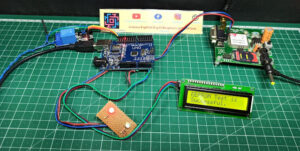
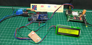
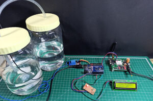
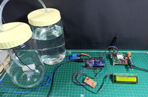
- when you turn on the system the LCD will display the welcome message and show the Real status of motor conduction.I mean Motor will be On And OFF.
- When you call the GSM Module They received the call and after 3 and 4 sec automatically cut the call the relay will turn On the motor and after a few sec the send feedback message will come “Motor Will be Turn On”.
- And if you call again the GSM Module Received the call and 3 and 4 sec later cut the call and the relay will be OFF motor Will be oFF After a few sec later the feedback message will come “motor will be Turn Off”
- The Red Led will Indicate the motor is OFF Conduction And the Green Led Will Indicate The Motor is On Conduction.
Video Tutorial
Related Projects:-




Sir “str” in this code was not declared, this shows after i put the code, please help