
Gps & Gsm location Tracking System Using Arduino
Women Safety Device With GPS Tracking
Introduction
Hi, Everyone Welcome To Our Blog. In this Project, I will explain the GPS & GSM location Tracking System Using Arduino. I used the Arduino nano micro controller GPS GSM Push Button And Buzzer.
A wide range of tracking systems has been developed tracking persons and Materials and displaying their position on a map, we can also use the system that has been developed to track the mobility of a human being. Nowadays tracking a person’s mobility has become a crucial issue these days be it tracking a criminal coming on payroll or a detective going to detect a case or any other utility.
In this project when you press the push button the GSM sends the proper GPS location to the particular mobile number. and you find out the proper global Positioning System for any Person
Bill of Materials
S.N | Components | Quantity | Link To Buy | |
1 | Arduino Nano | 1 | ||
2 | Gps Neo6m | 1 | ||
3 | Gsm (Sim-900A) | 1 | ||
4 | Buzzer | 1 | ||
5 | Push Button | 1 | ||
6 | 12v Power Supply | 1 |
Component Overview
Arduino Nano
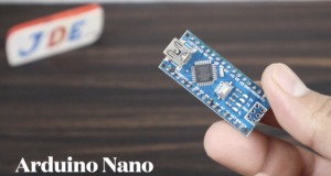
Arduino Nano is a small Size Board on this board, there is ATmega328p SMD Ic. There is a Total of 14 Digital pins and 8 Analog pins available to interface the Input And Output Connection.
I will Just explain The Pin Connection Where You Connected the Module pin in our Arduino Nano.
GPS Neo-6m Module
Arduino To GPS Module
D10 | Tx |
D9 | Rx |
5V | Vcc |
GND | GND |
GPS module U-Blox NEO 6M module and GPS antenna. The NEO-6 series is a family of stand-alone GPS receivers featuring the high-performance U-Blox 6 positioning engine. The I2C-compatible Display Data Channel (DDC) interface can be used either to access external devices with serial interface EEPROM or to interface with a host CPU. Its maximum bandwidth is 100kbit/s
Gsm Module (SIM 900A)
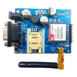
Arduino To GSM Module
D2 | Tx |
D3 | Rx |
5v | Vcc |
GND | GND |
GSM/GPRS modem is a digital mobile network that is widely used by mobile users. It is used to establish communication between a Controller and a GSM system. The modem is Coming RS232 interface, which allows to Connection PC as well as the microcontroller with the RS232 chip. The baud rate is configurable from 9600 through the AT command.
The GSM modem has having internal TCP/IP stack to enable you to connect with the internet via GPRS. It is suitable for SMS, voice as well as DATA transfer applications in the M2M interface. The onboard Regulate Power Supply allows us to connect a wide range of unregulated power supplies.
Using this modem, one can make audio calls, SMS, Read SMS, and attend the incoming calls and the internet through simple AT commands. Every command starts with “AT”. That’s why these are called AT commands. AT stands for “attention”.
Push Button
Arduino To Push Button
D6 | Push Button |
GND | GND |
Buzzer
Arduino To Buzzer
D8 | +5v (Vcc) |
GND | GND |
Library Installation
In This Project, You Want to Add a TinyGPS Library. Before You Uploading The Code.
Here I Just Provide The Github Link You Just Download The File Go to the Arduino IDE Go to the sketch section & click the Include Library.
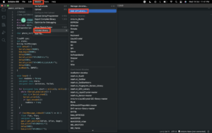
Next, You just Select the add.Zip Library And you just Upload the file in Arduino IDE.
System Overview
The current design is an embedded application system. Arduino is a based tracking system using GPS and GSM modules. This system is used for tracking and positioning any location by using the Global Positioning System (GPS) and Global System for mobile communication (GSM).
Tracking of Any Persons & Material is a process in which one can track the vehicle’s location in the form of latitude and longitude. GPS coordinates are the value of allocation.
Circuit Diagram & Connection
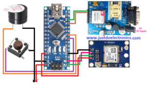
Source Code | Program
Before We Uploading The Code just Change The Mobile Number
|
1 |
char phone_no[] = "+9188305848xx"; |
Now We Uploading The Final Code
|
1 2 3 4 5 6 7 8 9 10 11 12 13 14 15 16 17 18 19 20 21 22 23 24 25 26 27 28 29 30 31 32 33 34 35 36 37 38 39 40 41 42 43 44 45 46 47 48 49 50 51 52 53 54 55 56 57 58 59 60 61 62 63 64 65 66 67 68 69 70 71 72 73 74 |
//Prateek //www.justdoelectronics.com #include <TinyGPS.h> #include <SoftwareSerial.h> #include <Wire.h> SoftwareSerial Gsm(9, 10); // RX, TX pins for GSM module char phone_no[] = "+91883058xxxx"; // Put Your phone number TinyGPS gps; int buttonState; unsigned long buttonPressTime; bool isSMSsent = false; void setup() { Serial.begin(9600); Gsm.begin(9600); Gsm.print("AT+CMGF=1\r"); delay(100); Gsm.print("AT+CNMI=2,2,0,0,0\r"); delay(100); pinMode(5, INPUT_PULLUP); } void loop() { bool newData = false; unsigned long chars; unsigned short sentences, failed; for (unsigned long start = millis(); millis() - start < 1000;) { while (Serial.available()) { char c = Serial.read(); Serial.print(c); // Output GPS data to the Serial Monitor if (gps.encode(c)) newData = true; // Check if there is new GPS data } } buttonState = digitalRead(5); if (buttonState == LOW) { // Button is pressed if (!isSMSsent) { buttonPressTime = millis(); float flat, flon; unsigned long age; gps.f_get_position(&flat, &flon, &age); Gsm.print("AT+CMGF=1\r"); delay(400); Gsm.print("AT+CMGS=\""); Gsm.print(phone_no); Gsm.println("\""); Gsm.println("Alert I Need help..."); Gsm.print("http://maps.google.com/maps?q=loc:"); Gsm.print(flat == TinyGPS::GPS_INVALID_F_ANGLE ? 0.0 : flat, 6); Gsm.print(","); Gsm.print(flon == TinyGPS::GPS_INVALID_F_ANGLE ? 0.0 : flon, 6); delay(200); Gsm.println((char)26); delay(200); Serial.println("SMS Sent"); isSMSsent = true; } } else { isSMSsent = false; delay(10); } Serial.println(failed); } |
Video Tutorial
If you are interested in more Video Plz Watch It
.





One Comment