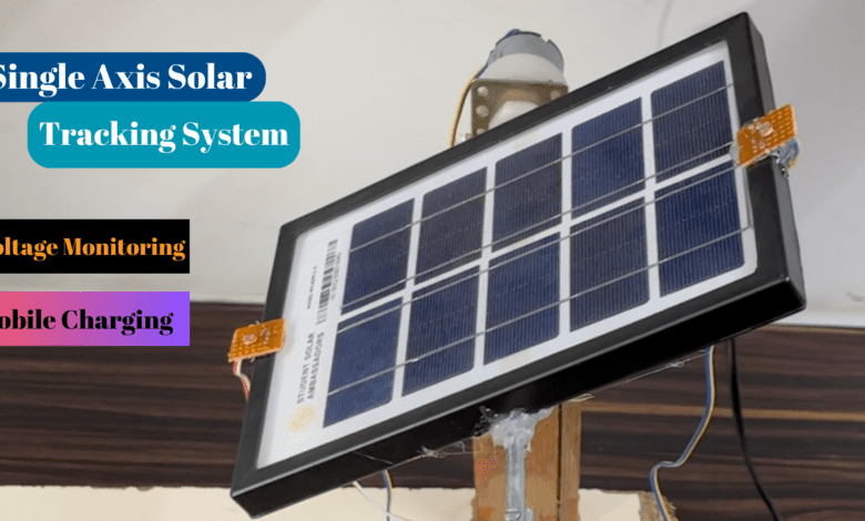
Solar Tracking System Using Arduino
solar tracking system using Arduino with mobile charging system
Introduction
In this article, we design a simple solar tracking project and make a small power bank to charge our mobile phones. here we used the Arduino nano microcontroller,l293 motor driver, and LDR sensor module.
The project is simple and is very used if any person faces the problem of charging a mobile battery, they use the system and charge the mobile phone in an emergency conduction.
Components
- The Arduino Nano is the open-source smallest Embedded Development board based on Atmega328 SMD Package Microcontroller.
- Arduino Nano is a low-cost microcontroller and so many GPIO Pin available.
Features:-
- Microcontroller Atmel ATmega328 SMD Package
- Operating Voltage – 5V
- Input Voltage 7-12V
- Input Voltage 6-20V
- Digital I/O Pins 14 (6 PWM output)
- Analog Input Pins -8
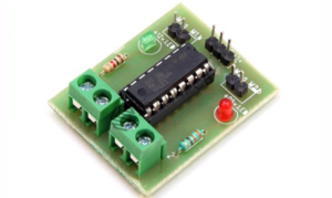
- L293D Motor Driver Module is a medium-power motor driver perfect for driving DC Motors.
- It uses the popular L293 motor driver IC. It can drive 4 DC motors on and off.
- Wide supply voltage: 4.5 V to 12 V.
- Max supply current: 600 mA per motor.
LDR Sensor Module
- LDR Sensor Module is used to detect the presence of light / measuring the intensity of light.
- The output of the module goes high in the presence of light and it becomes low in the absence of light.
- Using LM393 comparator chip, stable.
- Operating voltage 3.3V-5V.
lithium-ion Battery
Circuit Diagram
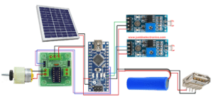
Here we designed a proper circuit diagram of the project now I will explain how you design the circuit in an easy method.
- The Solar panel provides the output of 12v DC and is connected to the Arduino nano Vin And GND Pin.
- L293 Motor Driver connected to the Pin Numbers D4 & D5 to the Arduino Nano Board.
- Now we connect the LDR Sensor Module to the PIN D3 & D2 in the Arduino Board.
The lithium-ion Battery is connected to the solar panel and USB-A Adapter.
If you want to charge the Mobile Phone then you connect the Mobile USB cable to the USB-A adapter.
Note:-
Plz, do a proper connection to the Positive (VCC) And Ground(GND) wire because if short then the solar panel has a chance to Dimage it.
Code
Now in a code, no libery is required to install it you copy the code in your Arduino IDE software and select the proper board and port.
Then click the upload button and make sure you connect the proper USB cable to your laptop or system.
|
1 2 3 4 5 6 7 8 9 10 11 12 13 14 15 16 17 18 19 20 21 22 23 24 25 26 27 28 29 30 |
//Prateek //www.justdoelectronics.com int ldr1 = 2; int ldr2 = 3; void setup() { Serial.begin(9600); pinMode(2, INPUT); pinMode(4, OUTPUT); pinMode(3, INPUT); pinMode(5, OUTPUT); } void loop() { if (digitalRead(2) == LOW) { digitalWrite(4, HIGH); Serial.println("motor moves forward "); } else if (digitalRead(3) == LOW) { digitalWrite(5, HIGH); Serial.println("motor moves backward "); } else { digitalWrite(4, LOW); digitalWrite(5, LOW); } } |
Projects Demo
Now I put the flashlight On the LDR Module then the value will change and the DC Motor Rotate the Clock and AntiClock Wise Direction.
The Battery will be stored and used to charge the mobile Phone.


