Introduction
In this article, we will explain how to create a Smart Dustbin using a few components like a 16×2 LCD, an ultrasonic sensor, a Sim800l module, a NEO-6m module, and the ESP8266 microcontroller.
This integration of hardware and software will enable us to monitor the status of the dustbin, Find out the Level of waste management, and provide real-time data for efficient collection and disposal.
Components Needed
- ESP8266 Controller
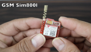
- GSM Module
- 16×2 LCD Display with I2C
- GPS Module
- Ultrasonic Sensor
- Wire
- Zero PCB
- 5V power supply
Component
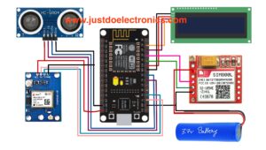
ESP8266
-
- VCC: Connected to the 5V power supply
- GND: Connected to the ground (GND)
LCD Display
-
- SDA: Connected to the SDA pin of the ESP8266 (D2)
- SCL: Connected to the SCL pin of the ESP8266 (D1)
- VCC: Connected to the 5V power supply (Vin)
- GND: Connected to the ground (GND)
Ultrasonic Sensor
-
- Trig: Connected to a digital pin (D6) of the ESP8266
- Echo: Connected to a digital pin (D5) of the ESP8266
- VCC: Connected to the 5V power supply
- GND: Connected to the ground (GND)
GSM Module
-
- RX: Connected to the TX pin (D4) of the ESP8266
- TX: Connected to the RX pin (D3) of the ESP8266
- VCC: Connected to the 5V power supply
- GND: Connected to the ground (GND)
Circuit Diagram
Source Code
LiquidCrystal_I2C
|
1 2 3 4 5 6 7 8 9 10 11 12 13 14 15 16 17 18 19 20 21 22 23 24 25 26 27 28 29 30 31 32 33 34 35 36 37 38 39 40 41 42 43 44 45 46 47 48 49 50 51 52 53 54 55 56 57 58 59 60 61 62 63 64 65 66 67 68 69 70 71 72 73 74 75 76 77 78 79 80 81 82 83 84 85 86 87 88 89 90 91 92 93 94 95 96 97 98 99 100 101 102 103 104 105 106 107 108 109 110 111 112 113 114 115 116 117 118 119 120 121 122 |
//Parteek //www.justdoelectronics.com #include <ESP8266WiFi.h> #include <SoftwareSerial.h> SoftwareSerial mySerial(D3, D4); #include <LiquidCrystal_I2C.h> LiquidCrystal_I2C lcd(0x27, 16, 2); const int trigPin = D6; const int echoPin = D5; const int led = D7; long duration; int distance; float level; const char *ssid = "Prateek"; const char *password = "#12345"; void send_event(const char *event); const char *host = "maker.ifttt.com"; const char *privateKey = "hUAAAz0AVvc6-NW1UmqWXXv6VQWmpiGFxx3sV5rnaM9"; WiFiServer server(80); void setup() { pinMode(trigPin, OUTPUT); pinMode(echoPin, INPUT); pinMode(led, OUTPUT); Serial.begin(9600); mySerial.begin(9600); lcd.init(); lcd.backlight(); lcd.setCursor(0, 0); lcd.print(" Smart "); lcd.setCursor(0, 1); lcd.print(" Dustbin"); delay(3000); lcd.clear(); Serial.print("Connecting to Wifi Network"); Serial.println(ssid); WiFi.begin(ssid, password); while (WiFi.status() != WL_CONNECTED) { delay(500); Serial.print("."); } Serial.println(""); Serial.println("Successfully connected to WiFi."); Serial.println("IP address is : "); Serial.println(WiFi.localIP()); server.begin(); Serial.println("Server started"); } void loop() { digitalWrite(trigPin, LOW); delayMicroseconds(2); digitalWrite(trigPin, HIGH); delayMicroseconds(10); digitalWrite(trigPin, LOW); duration = pulseIn(echoPin, HIGH); distance = duration * 0.0340 / 2; Serial.println("Distance"); Serial.println(distance); level = ((25 - distance) / 25.0) * 100; //25 Serial.println("level"); Serial.println(level); lcd.setCursor(0, 0); lcd.print(" Smart Dustbin"); lcd.setCursor(0, 1); lcd.print(" Level"); lcd.setCursor(8, 1); lcd.print(level); digitalWrite(led, LOW); delay(200); WiFiClient client = server.available(); if (level >= 80) { SendMessage(); digitalWrite(led, HIGH); send_event("jar_event"); } } void send_event(const char *event) { Serial.print("Connecting to "); Serial.println(host); // Use WiFiClient class to create TCP connections WiFiClient client; const int httpPort = 80; if (!client.connect(host, httpPort)) { Serial.println("Connection failed"); return; } // We now create a URI for the request String url = "/trigger/"; url += event; url += "/with/key/"; url += privateKey; Serial.print("Requesting URL: "); Serial.println(url); // This will send the request to the server client.print(String("GET ") + url + " HTTP/1.1\r\n" + "Host: " + host + "\r\n" + "Connection: close\r\n\r\n"); while (client.connected()) { if (client.available()) { String line = client.readStringUntil('\r'); Serial.print(line); } else { // No data yet, wait a bit delay(50); }; } Serial.println(); Serial.println("closing connection"); client.stop(); } void SendMessage() { Serial.println("Dustbin Full"); mySerial.println("AT+CMGF=1"); delay(1000); mySerial.println("AT+CMGS=\"+9188305848xx\"\r"); delay(1000); mySerial.println("Dustbin1 Is Full Plz Remove Dustbin https://www.google.com/maps?q "); delay(100); mySerial.println((char)26); delay(1000); } |
Video
Conclusion
This smart solution allows for real-time monitoring of the dustbin’s fill level, sends alerts to the appropriate authorities, and provides location data for efficient waste management.
More Project


Great work boss. I really love the article
.please the GPS was not included in the code