Line Follower Robot Using Arduino & RC-522 RFID
Introduction
Industrial line follower robots play a crucial role in automated systems, allowing them to navigate and perform tasks efficiently. In this article, we will explore the process of building an industrial line follower robot using RFID (Radio Frequency Identification) technology and the TCRT5000 IR sensor. The Arduino Nano microcontroller will serve as the brain of the robot, enabling it to detect and follow lines accurately.
- Line Detection: The TCRT5000 IR sensor detects the line by emitting infrared light and measuring the reflected light intensity. When the phototransistor detects a high intensity of reflected light, it signifies that the sensor is over a white surface (or no line). Conversely, a low intensity of reflected light indicates that the sensor is over the line.
- Programming the Arduino Nano: Install the necessary libraries for the TCRT5000 IR sensor and RFID module in the Arduino IDE. Write a program to read the sensor data and adjust the motor speeds accordingly to follow the line accurately. Implement appropriate control algorithms such as PID (Proportional-Integral-Derivative) for smoother line tracking.
- RFID Integration: With the RFID module, you can introduce additional functionality to the robot, such as object identification or navigation based on RFID tags. Program the Arduino Nano to read the RFID tags and execute specific actions based on the detected tags.
Components Needed
- Arduino Nano
- RC-522 RFID Module
- BO Motor
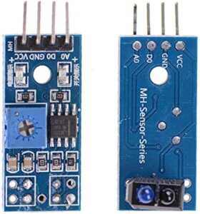
- TCRT5000 IR Sensor
- Rechargeable Battery
- L298N Motor Driver
- Buzzer
Arduino Nano

- The Arduino Nano is a compact and powerful microcontroller board that will serve as the central processing unit of our robot. Connect it to your computer and install the Arduino IDE (Integrated Development Environment) to program it.
Bo Motors
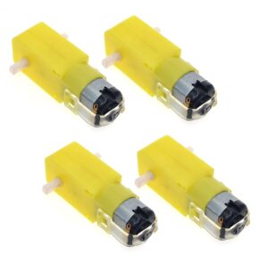
- Connect the motors to the Arduino Nano using a suitable motor driver or H-bridge module. These motors will control the movement of the robot, allowing it to follow the line accurately.
TCRT5000 IR Sensor
- The TCRT5000 sensor operates based on the reflection of infrared light. The infrared LED emits infrared light, and the phototransistor detects the intensity of the reflected light. The behaviour of the reflected light determines whether the sensor is over a line or not.
- Line Detection When the infrared light emitted by the LED falls on a white or reflective surface (e.g., the floor), a significant portion of the light is reflected back to the phototransistor. This causes the phototransistor to conduct more current, resulting in a logical high or a higher voltage output.
- Conversely, when the sensor is positioned over a dark or non-reflective surface (e.g., a black line), less light is reflected back to the phototransistor. Consequently, the phototransistor conducts less current, leading to a logical low or a lower voltage output.
- By monitoring the output of the phototransistor, it is possible to determine whether the sensor is positioned over a line or not. This information can be used to guide the movement of a line follower robot along the desired path.
- The TCRT5000 IR sensor is a popular choice for line detection. It consists of an IR LED and a phototransistor. Wire the sensor to the Arduino Nano following the instructions provided in the sensor’s datasheet.
RFID Module(RC-522)
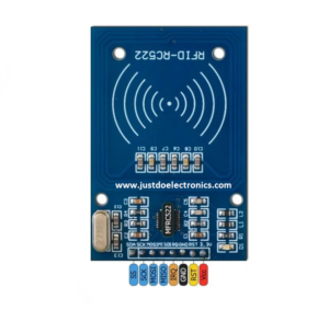
The RC522 module operates in the 13.56 MHz frequency range and communicates using the SPI (Serial Peripheral Interface) protocol. It consists of an integrated circuit that includes the RF front end, digital logic, and a command set for communicating with the Arduino or any other microcontroller.
The RC522 module typically has eight pins, which are
- 3.3V: This pin is used to provide power to the module. Connect it to a 3.3V power source.
- RST (Reset): This pin is used to reset the module. Connect it to a digital pin on the Arduino to control the reset operation.
- GND: This pin is connected to the ground (0V) of the power supply.
- IRQ: This pin is an optional interrupt pin. It can be connected to a digital pin on the Arduino if you want to use interrupts for specific events.
- MISO (Master In Slave Out): This pin is used for SPI communication and data transmission from the module to the Arduino.
- MOSI (Master Out Slave In): This pin is used for SPI communication and data transmission from the Arduino to the module.
- SCK (Serial Clock): This pin is used for SPI clock synchronization between the module and the Arduino.
- SDA (Serial Data): This pin is used for SPI communication and is responsible for transmitting commands, data, and acknowledgements between the module and the Arduino.
The RC522 module provides a rich set of functionalities for RFID communication. Some of the main functions include
- RFID Tag/Card Detection: The module can detect and communicate with RFID tags or cards that are brought within its operating range.
- Tag/Card Identification: It can read the unique identification number (UID) of RFID tags or cards. This UID is typically used for identification and tracking purposes.
- Data Read/Write: The RC522 module can read and write data to compatible RFID tags or cards. This allows you to store and retrieve information on the tags/cards.
- Security Features: The module supports various security features, such as cryptographic authentication and access control, to ensure secure communication with authorized tags/cards.
- Incorporating RFID technology into the line follower robot adds additional functionality. Connect the RFID module to the Arduino Nano according to the module’s documentation.
L298N Motor Driver
The L298N motor driver provides two H-bridges, which are circuits that enable bidirectional control of motors. Each H-bridge consists of four transistors that can be switched on and off to control the flow of current through the motor windings. By controlling the state of these transistors, the L298N can control the speed and direction of the connected motors.
- Motor Power Supply:
- VMS: This pin is connected to the positive terminal of the motor power supply (typically 5V to 35V).
- Control Pins for Motor A:
- ENA: Enable pin for Motor A. This pin is used to control the speed of Motor A using PWM (Pulse Width Modulation) signals.
- IN1: Input pin 1 for Motor A. This pin controls the direction of rotation for Motor A.
- IN2: Input pin 2 for Motor A. This pin controls the direction of rotation for Motor A.
- Control Pins for Motor B:
- ENB: Enable pin for Motor B. This pin is used to control the speed of Motor B using PWM signals.
- IN3: Input pin 1 for Motor B. This pin controls the direction of rotation for Motor B.
- IN4: Input pin 2 for Motor B. This pin controls the direction of rotation for Motor B.
- Power Supply:
- VCC: This pin is connected to the positive terminal of the logic power supply (typically 5V).
- GND: This pin is connected to the ground (0V) of both the motor and logic power supplies.
To control the motors using the L298N motor driver, you need to provide suitable input signals to the control pins. The control signals determine the direction of rotation and speed of the motors. The steps involved in motor control are as follows
- Power Supply: Connect the motor power supply (VMS) to the positive terminal of the motors and the ground (GND) of the power supply to the ground of the motors.
- Logic Power Supply: Connect the logic power supply (VCC) to a 5V power source and connect the ground (GND) of the logic power supply to the ground of the microcontroller and other control circuitry.
- Control Pins: Connect the control pins (ENA, IN1, IN2, ENB, IN3, IN4) to suitable digital output pins of a microcontroller (e.g., Arduino) or other control circuitry.
- Motor Control Logic: Use the microcontroller to provide appropriate logic signals to the control pins. For example, to make Motor A rotate forward set IN1 to HIGH and IN2 to LOW. To rotate it in reverse, set IN1 to LOW and IN2 to HIGH. Similarly, control the rotation of Motor B using the IN3 and IN4 pins.
- Speed Control: Use the PWM-capable pins of the microcontroller to provide PWM signals to the ENA and ENB pins. By varying the duty cycle of the PWM signals, you can control the speed of the motors.
Power Supply
- we will attach the 12v Supply with the help of the rechargeable battery.
- Ensure that the Arduino Nano, motors, and other components receive a suitable power supply to operate smoothly and reliably.
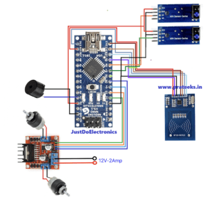
Circuit Diagram
Code
|
1 2 3 4 5 6 7 8 9 10 11 12 13 14 15 16 17 18 19 20 21 22 23 24 25 26 27 28 29 30 31 32 33 34 35 36 37 38 39 40 41 42 43 44 45 46 47 48 49 50 51 52 53 54 55 56 57 58 59 60 61 62 63 64 65 66 67 68 69 70 71 72 73 74 75 76 77 78 79 80 81 82 83 84 85 86 87 88 89 90 91 92 93 94 95 96 97 98 |
#include <SPI.h> #include <MFRC522.h> #define LINESENSOR1 6 #define LINESENSOR2 7 #define BUZZER A0 #define MOTOR1A 2 #define MOTOR1B 3 #define MOTOR2A 4 #define MOTOR2B 5 #define RFID_SDA 10 #define RFID_SCK 13 #define RFID_MOSI 11 #define RFID_MISO 12 #define RFID_RST 9 #define STOP_TIME 3000 #define BEEP_LENGTH 200 #define MOTOR_SPEED 110 #define MINIMUM_TIME_BETWEEN_CARDS 2000 MFRC522 mfrc522(10, 9); long int last_card_read; #define COMMANDS_LENGTH 4 char* Type[4] = { "Stop", "Beep&stop", "Beep&ignore", "Stop" }; int Value[4] = { 3000, 1000, 0, 5000 }; char* CardID[4] = { "xx xx xx xx", "xx xx xx xx", "xx xx xx xx", "xx xx xx xx" }; void setup() { SPI.begin(); mfrc522.PCD_Init(); pinMode(LINESENSOR1, INPUT); pinMode(LINESENSOR2, INPUT); pinMode(LINESENSOR3, INPUT); pinMode(BUZZER, OUTPUT); pinMode(MOTOR1A, OUTPUT); pinMode(MOTOR1B, OUTPUT); pinMode(MOTOR2A, OUTPUT); pinMode(MOTOR2B, OUTPUT); pinMode(DISTANCESENSOR, INPUT); } void loop() { if (digitalRead(LINESENSOR1) == LOW && digitalRead(LINESENSOR2) == HIGH && digitalRead(LINESENSOR3) == LOW) { Forward(); } else if (digitalRead(LINESENSOR1) == HIGH && digitalRead(LINESENSOR2) == LOW && digitalRead(LINESENSOR3) == LOW) { Left(); delay(20); } else if (digitalRead(LINESENSOR1) == LOW && digitalRead(LINESENSOR2) == LOW && digitalRead(LINESENSOR3) == HIGH) { Right(); delay(20); } if (millis() - last_card_read >= MINIMUM_TIME_BETWEEN_CARDS) { if (!mfrc522.PICC_IsNewCardPresent()) { return; } if (!mfrc522.PICC_ReadCardSerial()) { return; } String content = ""; for (byte i = 0; i < mfrc522.uid.size; i++) { Serial.print(mfrc522.uid.uidByte[i] < 0x10 ? " 0" : " "); Serial.print(mfrc522.uid.uidByte[i], HEX); content.concat(String(mfrc522.uid.uidByte[i] < 0x10 ? " 0" : " ")); content.concat(String(mfrc522.uid.uidByte[i], HEX)); } content.toUpperCase(); content = content.substring(1); for (int a = 0; a < COMMANDS_LENGTH; a++) { last_card_read = millis(); if (content == CardID[a]) { if (Type[a] == "Stop") { Stop(); delay(Value[a]); } else if (Type[a] == "Beep&stop") { digitalWrite(BUZZER, HIGH); Stop(); delay(Value[a]); digitalWrite(BUZZER, LOW); } else if (Type[a] == "Beep&ignore") { Stop(); digitalWrite(BUZZER, HIGH); delay(500); digitalWrite(BUZZER, LOW); } else if (Type[a] == "Ignore") { } } } } } |
Video
RC-522 RFID Related More Project
Conclusion
- By combining the TCRT5000 IR sensor for line detection, RFID technology for object identification, and the Arduino Nano for control, we can create an industrial line follower robot capable of precise navigation and efficient task execution.
- Building such a robot not only provides a hands-on learning experience but also opens up opportunities for automation in various industrial applications.
