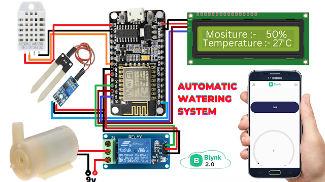
Smart Irrigation System Using New Blynk App
Smart Irrigation System Using ESP8266 & New Blynk App
Introduction
Hi Everyone, in this project we will discuss an IOT-based irrigation System using the new Blynk app.
The smart irrigation system has so many scopes to automate the whole irrigation system. here we are making a lot-based smart irrigation system using the ESP8266 Controller and DHT22Sensor.
It will also send the data to the new Blynk application to keep track of the land condition. the system will consist of a water pump which will be used the sprinkle water depending on the land’s condition such as moisture, temperature, and Humidity.
First, we are going to see why we are doing then we see which components we used, and after we see the step-by-step procedure to make this system.
Why are you making this?
we are doing this is controlling our small farm activity independently from anywhere in the world. also, we can monitor the real-time data on the screen of our mobile.
These are the Advantages of this System
- Should work autonomously by sensing soil moisture levels.
- It also Operates battery or solar.
- control the whole system in an automated fashion.
- Be extendable to any number of zones relatively easily.
Bill Of Materials
S.N | Component | Quanitity | LInk To Buy |
1 | ESP8266 | 1 | |
2 | 16x2 LCD Display | 1 | |
3 | DHT22 Sensor | 1 | |
4 | Soil Mositure Sensor | 1 | |
5 | 5v Relay Module | 1 | |
6 | Water Pump | 1 | |
7 | Zero PCB | 1 |
ESP8266 (NodeMCU)
Here We just Show the Pin Diagram Of The ESP8266 Board On the Right showing all Digital GPIO Pins available.
In this ESP8266 Board Is Only One Analog Pin available And They are connected to the Soil Moisture Sensor.
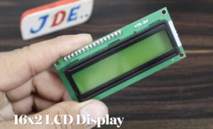
16×2 LCD Display
Here we used the 16×2 LCD Display and they will be connected to the I2C Protocol
- VCC-5V
- GND-GND
- SDA-A4
- SCL-A5
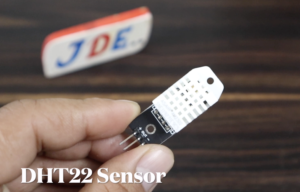
DHT22 Sensor
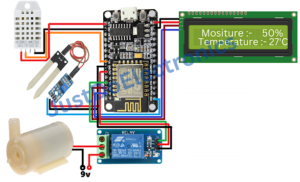
It Measuring The Temperature And Humidity And They Will be Connected To The Pin Number D3
- VCC-5V
- Digital Pin-D3
- GND-GND
Soil Moisture Sensor
Soil Moisture Sensor measures the soil water level in the earth and sends data to Blynk App The Will is connected to Pin Number A0.
- VCC-5V
- Analog Pin -A0
- GND- GND
5V 1-Channel Motor
Here We Used The 5v relay module and they are well connected to PIN D5.
- VCC – 5V
- Relay Pin – D5
- GND – GND
DC Water Pump
Now I will Just Show The Connection between The Water Pump and the Relay Module
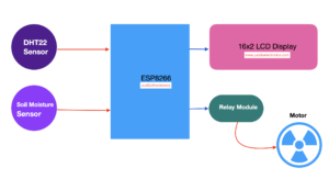
Block Diagram
Circuit Diagram
Blynk App Setup
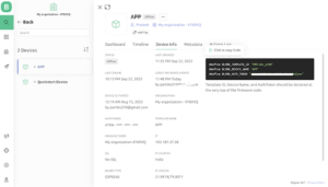
Now, we created the New Blynk Application
STEP 1
STEP2
STEP3
STEP4
Source Code
Before You Upload the code You just change these things
|
1 2 3 |
char auth[] = "uBTcT8j6LZTNPvcxkRg9Y"; char ssid[] = "JDE"; char pass[] = "par12345"; |
Now Select The Proper Board And then Upload The Code
|
1 2 3 4 5 6 7 8 9 10 11 12 13 14 15 16 17 18 19 20 21 22 23 24 25 26 27 28 29 30 31 32 33 34 35 36 37 38 39 40 41 42 43 44 45 46 47 48 49 50 51 52 53 54 55 56 57 58 59 60 61 62 63 64 65 66 67 68 69 70 71 72 73 74 75 76 77 78 79 80 81 82 83 84 85 86 87 88 89 90 91 |
//Prateek //www.justdoelectronics.com #include <LiquidCrystal_I2C.h> #define BLYNK_PRINT Serial #include <ESP8266WiFi.h> #include <BlynkSimpleEsp8266.h> #include <DHT.h> LiquidCrystal_I2C lcd(0x27, 16, 2); char auth[] = "uBTcT8j6LZTNPvcxkRg9Y"; char ssid[] = "JDE"; char pass[] = "par12345"; BlynkTimer timer; bool Relay = 0; DHT dht(D3, DHT22); #define sensor A0 #define waterPump D5 void setup() { Serial.begin(9600); pinMode(waterPump, OUTPUT); digitalWrite(waterPump, HIGH); lcd.begin(); lcd.backlight(); dht.begin(); Blynk.begin(auth, ssid, pass, "blynk.cloud", 80); lcd.setCursor(1, 0); lcd.print("System Loading"); for (int a = 0; a <= 15; a++) { lcd.setCursor(a, 1); lcd.print("."); delay(500); } lcd.clear(); timer.setInterval(100L, DHT22sensor); timer.setInterval(100L, soilMoistureSensor); } //Get the button value BLYNK_WRITE(V7) { Relay = param.asInt(); if (Relay == 1) { digitalWrite(waterPump, LOW); } else { digitalWrite(waterPump, HIGH); } } //Get the soil moisture values void soilMoistureSensor() { int value = analogRead(sensor); value = map(value, 0, 1024, 0, 100); value = (value - 100) * -1; Blynk.virtualWrite(V8, value); lcd.setCursor(0, 0); lcd.print("Moisture :"); lcd.print(value); lcd.print(" "); } void DHT22sensor() { float h = dht.readHumidity(); float t = dht.readTemperature(); if (isnan(h) || isnan(t)) { Serial.println("Failed to read from DHT sensor!"); return; } lcd.setCursor(0, 1); lcd.print("T:"); lcd.print(t); lcd.setCursor(8, 1); lcd.print("H:"); lcd.print(h); } void loop() { Blynk.run(); //Run the Blynk library timer.run(); //Run the Blynk timer } |
Demo Of Project
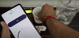
Now Is the Time To test our project. we just turn on the Power Supply and open the new blynk app.
Now Is motor will be Off-conduction and the moisture level is also 0.
when I put the moisture sensor in the water motor will be on and the blank app show the moisture level
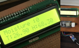
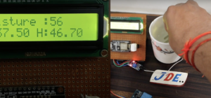
Now we will just display the DHT22 sensor data in LCD Display and is show that the temperature 26 c and Humidity will be 68%
Now the Moisture level will display o in a 16×2 LCD because of the sensor is not detecting water.
when I put the sensor in water the display the moisture level in the LCD Display is 56%
If you are interested in More IOT projects Then Check Here













Bonjour,
Je souhaiterais en savoir plus sur la manière dont vous avez développé votre application Blynk 2.0.
J’ai beaucoup apprécié votre projet et envisage de le reprendre. Pourriez-vous me partager davantage de détails sur sa conception et les étapes clés de son développement ?
Merci d’avance pour votre retour.
Cordialement !
Mass GNING