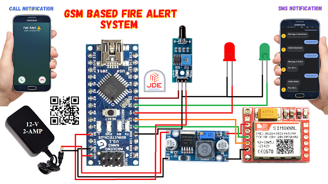
Fire Alert System Using Arduino & GSM
step by step guide for Fire Alert System Using Arduino
Introduction
In this article, we will guide you through the process of building a fire alert system using the Arduino and GSM modules. This system will provide real-time call and SMS alerts, ensuring the response is damaged. Fire accidents can have devastating consequences, making it crucial to have an efficient fire alert system in place.
Components Required
S.N | Component's | Quantity | Link to Buy |
1 | Arduino Nano | 1 | |
2 | GSM module (SIM800l) | 1 | |
3 | LM2596 Step Down Conveter | 1 | |
4 | Flame Sensor | 1 | |
5 | Red Led | 1 | |
6 | Green Led | 1 | |
7 | Zero PCB | 1 | |
8 | 9v Power Supply | 1 |
Arduino Nano
- The Arduino Nano has used an ATmega328P microcontroller chip.
- The ATmega328P operates at a clock speed of 16 MHz.
- Flash memory 32KB.
- SRAM of 2KB.
- 1KB of EEPROM.
GSM module (SIM800l)
- The GSM module is a compact device that enables communication over the GSM network. It uses a Subscriber Identity Module (SIM) card to establish a connection with the cellular network.
- The SIM800L GSM module requires a stable and regulated power supply of around 3.7-4.2V.
LM2596 Step Down Conveter
- LM2596 Step-Down Converter: The LM2596 is a popular step-down (buck) voltage regulator IC that can efficiently convert a higher input voltage to a lower, regulated output voltage. It is capable of handling input voltages higher than the desired output voltage, making it suitable for a wide range of power supply applications.
- Voltage Regulation: The LM2596 Step Down Converter can regulate the output voltage using a potentiometer to set the desired voltage level.
- Adjust the output voltage to match the required voltage range of the SIM800L GSM module (3.7-4.2V) by turning the potentiometer.
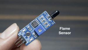
Flame Sensor
- The working flame sensor, at the top, is a photodiode available and detects the fire. if the fire is detected the photodiode anode pin is high and is given to the signal of LM393 IC.
- If the fire is detected The Digital value is LOW(0v) and if not detected any fire the output value is HIGH(5v) and the output pin is connected to any digital pin of a microcontroller like Arduino.
- if you are more interested to know how the flame sensor work just go through the article.
The Flame Sensor typically has three pins: VCC, GND, and OUT.
- VCC: The pin to connect to a positive terminal (5V).
- GND: The pin to connect to a ground terminal (0V).
- OUT: The pin to connect to a digital input pin of the microcontroller.
- This pin outputs a digital signal (HIGH or LOW) based on the presence or absence of flames.
Circuit Diagram
Arduino Nano
-
- Connect the power (VCC) and ground (GND) pins of the Arduino Nano to the respective power and ground rails of the breadboard or power supply.
- Connect pin 2 of the Arduino Nano to the RX pin of the GSM SIM800L module.
- Connect pin 3 of the Arduino Nano to the TX pin of the GSM SIM800L module.
- Connect pin 6 of the Arduino Nano to the signal pin of the fire sensor.
- Connect pin 3 of the Arduino Nano to the LED for SMS indication.
- Connect pin 4 of the Arduino Nano to the LED for call indication.
GSM SIM800L Module
-
- Connect the power (3.7V for LM2596) and ground (GND) pins of the GSM SIM800L module to the respective power and ground rails of the breadboard or power supply.
- Connect the TX pin of the GSM SIM800L module to pin 2 of the Arduino Nano.
- Connect the RX pin of the GSM SIM800L module to pin 3 of the Arduino Nano.
Fire Sensor
-
- Connect the VCC pin of the fire sensor to the power rail of the breadboard or power supply.
- Connect the GND pin of the fire sensor to the ground rail of the breadboard or power supply.
- Connect the signal pin of the fire sensor to pin 6 of the Arduino Nano.
LEDs
-
- Connect the positive leg (anode) of the SMS LED to pin 3 of the Arduino Nano.
- Connect the positive leg (anode) of the call LED to pin 4 of the Arduino Nano.
- Connect the negative leg (cathode) of both LEDs.
Code
|
1 2 3 4 5 6 7 8 9 10 11 12 13 14 15 16 17 18 19 20 21 22 23 24 25 26 27 28 29 30 31 32 33 34 35 36 37 38 39 40 41 42 43 44 45 46 47 48 49 50 51 52 53 54 55 56 57 58 59 60 61 62 63 64 65 66 67 68 69 70 71 72 73 74 75 76 77 78 79 80 81 82 83 84 85 86 87 88 89 90 91 92 93 94 95 96 97 98 99 100 101 102 103 104 105 106 107 108 109 110 111 112 113 114 115 116 117 118 119 120 121 122 123 124 125 126 127 128 129 130 131 132 133 134 135 136 137 138 139 140 141 142 143 144 145 146 147 148 |
//Prateek //https://justdoelectronics.com //https://www.youtube.com/c/JustDoElectronics/videos #include <EEPROM.h> #include <SoftwareSerial.h> SoftwareSerial GSM(2, 3); char phone_no[] = "+9188305848xx"; #define sensorPin 6 #define led_sms 3 #define led_call 4 int read_value; int sms_Status, call_Status; int flag = 0; int var_1 = 0, var_2 = 0; char input_string[15]; void setup() { Serial.begin(9600); GSM.begin(9600); pinMode(sensorPin, INPUT); pinMode(led_sms, OUTPUT); pinMode(led_call, OUTPUT); Serial.println("Initializing...."); initModule("AT", "OK", 1000); initModule("ATE1", "OK", 1000); initModule("AT+CPIN?", "READY", 1000); initModule("AT+CMGF=1", "OK", 1000); initModule("AT+CNMI=2,2,0,0,0", "OK", 1000); Serial.println("Initialized Successfully"); //Prateek //wwww.prateeks.in //https://www.youtube.com/c/JustDoElectronics/videos sendSMS(phone_no, "Start GSM Fire Alert System"); sms_Status = EEPROM.read(1); call_Status = EEPROM.read(2); } void loop() { readSMS(); read_value = digitalRead(sensorPin); if (read_value == 1) { flag = 0; } else { if (flag == 0) { flag = 1; if (sms_Status == 1) { sendSMS(phone_no, "Fire Alert...."); } delay(1000); if (call_Status == 1) { callUp(phone_no); } } delay(1000); } if (var_1 == 1) { if (!(strncmp(input_string, "Sms On", 6))) { sms_Status = 1; EEPROM.write(1, sms_Status); sendSMS(phone_no, "Message is Active"); } else if (!(strncmp(input_string, "Sms Off", 7))) { sms_Status = 0; EEPROM.write(1, sms_Status); sendSMS(phone_no, "Message is Deactivate"); } else if (!(strncmp(input_string, "Call On", 7))) { call_Status = 1; EEPROM.write(2, call_Status); sendSMS(phone_no, "Call is Active"); } else if (!(strncmp(input_string, "Call Off", 8))) { call_Status = 0; EEPROM.write(2, call_Status); sendSMS(phone_no, "Call is Deactivate"); } var_1 = 0; var_2 = 0; } digitalWrite(led_sms, sms_Status); digitalWrite(led_call, call_Status); } void sendSMS(char *number, char *msg) { GSM.print("AT+CMGS=\""); GSM.print(number); GSM.println("\"\r\n"); delay(500); GSM.println(msg); delay(500); GSM.write(byte(26)); delay(5000); } void callUp(char *number) { GSM.print("ATD + "); GSM.print(number); GSM.println(";"); delay(1000); } void readSMS() { while (GSM.available() > 0) { if (GSM.find("/123")) { delay(1000); while (GSM.available()) { char input_char = GSM.read(); input_string[var_2++] = input_char; if (input_char == '/') { var_1 = 1; return; } } } } } void initModule(String cmd, char *res, int t) { while (1) { Serial.println(cmd); GSM.println(cmd); delay(100); while (GSM.available() > 0) { if (GSM.find(res)) { Serial.println(res); delay(t); return; } else { Serial.println("Error"); } } delay(t); } } |
Libraries and Definitions
The code includes the necessary libraries.
- EEPROM.h
- SoftwareSerial.h
|
1 2 3 4 5 6 7 8 9 |
#include <EEPROM.h> #include <SoftwareSerial.h> SoftwareSerial GSM(2, 3); char phone_no[] = "+9188305848xx"; #define sensorPin 6 #define led_sms 3 #define led_call 4 |
Variable Declaration and Initialization
- Various variables are declared to store the status of SMS and call functions.
|
1 2 3 4 5 |
int read_value; int sms_Status, call_Status; int flag = 0; int var_1 = 0, var_2 = 0; char input_string[15]; |
Setup Function
-
- Pin modes are set for the flame sensor input and LED outputs.
- The initial SMS is sent to the specified phone number to indicate the start of the system.
- The previous status of SMS and call functionalities is retrieved from EEPROM memory.
|
1 2 3 4 5 6 7 8 9 10 11 12 13 14 15 16 17 18 19 20 21 22 23 |
void setup() { Serial.begin(9600); GSM.begin(9600); pinMode(sensorPin, INPUT); pinMode(led_sms, OUTPUT); pinMode(led_call, OUTPUT); Serial.println("Initializing...."); initModule("AT", "OK", 1000); initModule("ATE1", "OK", 1000); initModule("AT+CPIN?", "READY", 1000); initModule("AT+CMGF=1", "OK", 1000); initModule("AT+CNMI=2,2,0,0,0", "OK", 1000); Serial.println("Initialized Successfully"); //Prateek //wwww.prateeks.in //https://www.youtube.com/c/JustDoElectronics/videos sendSMS(phone_no, "Start GSM Fire Alert System"); sms_Status = EEPROM.read(1); call_Status = EEPROM.read(2); } |
Loop Function
-
readSMS()the function is called to check for incoming SMS messages and process them.- The value of the flame sensor input is read.
|
1 2 3 4 5 6 7 8 9 10 11 12 13 14 15 16 17 18 19 20 21 22 23 24 25 26 27 28 29 30 31 32 33 34 35 36 37 38 39 40 41 42 43 44 45 |
void loop() { readSMS(); read_value = digitalRead(sensorPin); if (read_value == 1) { flag = 0; } else { if (flag == 0) { flag = 1; if (sms_Status == 1) { sendSMS(phone_no, "Fire Alert...."); } delay(1000); if (call_Status == 1) { callUp(phone_no); } } delay(1000); } if (var_1 == 1) { if (!(strncmp(input_string, "Sms On", 6))) { sms_Status = 1; EEPROM.write(1, sms_Status); sendSMS(phone_no, "Message is Active"); } else if (!(strncmp(input_string, "Sms Off", 7))) { sms_Status = 0; EEPROM.write(1, sms_Status); sendSMS(phone_no, "Message is Deactivate"); } else if (!(strncmp(input_string, "Call On", 7))) { call_Status = 1; EEPROM.write(2, call_Status); sendSMS(phone_no, "Call is Active"); } else if (!(strncmp(input_string, "Call Off", 8))) { call_Status = 0; EEPROM.write(2, call_Status); sendSMS(phone_no, "Call is Deactivate"); } var_1 = 0; var_2 = 0; } digitalWrite(led_sms, sms_Status); digitalWrite(led_call, call_Status); } |
send sms Function
-
- This function is responsible for sending an SMS to the specified phone number.
|
1 2 3 4 5 6 7 8 9 10 |
void sendSMS(char *number, char *msg) { GSM.print("AT+CMGS=\""); GSM.print(number); GSM.println("\"\r\n"); delay(500); GSM.println(msg); delay(500); GSM.write(byte(26)); delay(5000); } |
callUp Function
-
- This function is responsible for making a call to the specified phone number.
- AT commands are sent to the GSM module to initiate the call to the recipient number.
|
1 2 3 4 5 6 |
void callUp(char *number) { GSM.print("ATD + "); GSM.print(number); GSM.println(";"); delay(1000); } |
read sms Function
-
- This function is used to read incoming SMS messages.
- It checks if the received SMS contains a specific keyword.
|
1 2 3 4 5 6 7 8 9 10 11 12 13 14 15 16 17 18 |
void readSMS() { while (GSM.available() > 0) { if (GSM.find("/123")) { delay(1000); while (GSM.available()) { char input_char = GSM.read(); input_string[var_2++] = input_char; if (input_char == '/') { var_1 = 1; return; } } } } } |
Video
Conclusion
Fire alert system using the Arduino Nano can significantly improve response times and reduce the damage caused by fire accidents. With real-time call and SMS alerts, emergency contacts can be immediately notified, allowing them to take prompt action.
More Arduino Tutorial
- Fingerprint Sensor-Based Biometric Security System
- Rfid And Fingerprint Based Bike And Car Ignition System
- Fingerprint And Alcohol Sensor-Based Bike Ignition System
- Fingerprint And Rfid Based Bike And Car Ignition Systems
- Soil Moisture Sensor With Arduino
- DS18B20 Sensor With Arduino
- Water Level Sensor With Arduino
- Rain Sensor With Arduino
- BMP-180 Sensor With Arduino
- Smart Bike And Car Starter


