Arduino Projects
Vehicle Location Tracker Using Arduino
step by step guide how you make vehicle location tracking system
Introduction
- In this article, we’ll explore how to build a GSM and GPS-based vehicle anti-locking system using Arduino.
- This project aims to enhance vehicle security by automatically locking the vehicle and sending its location to the owner’s mobile phone in case of theft access.
- The system leverages a GPS module to track the vehicle’s real-time location and a GSM module to send SMS alerts.
- The Vehicle Location Tracking System is an innovative solution that uses Arduino and it enables real-time tracking and remote control of a vehicle.
- This article will explain the completed process of the projects and explain all components in detail.
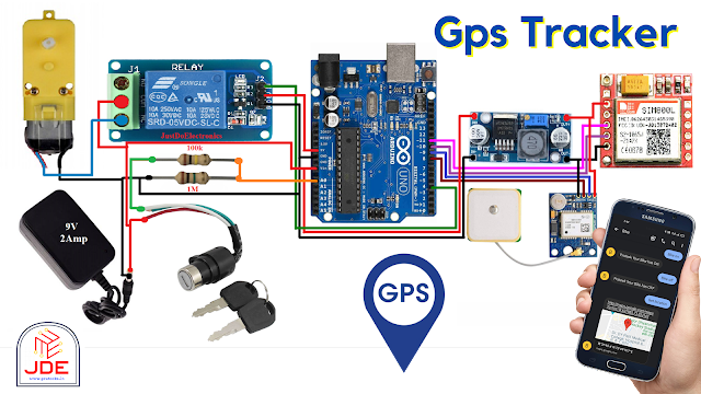
Circuit Components
S.N | Components | Quantity |
1 | Arduino Board | 1 |
2 | GSM module (SIM800l) | 1 |
3 | GPS module (NEO-6M) | 1 |
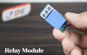
4 | Ignition switch (relay module) | 1 |
5 | Ignition sensor | 1 |
6 | 100k,1M | 1 |
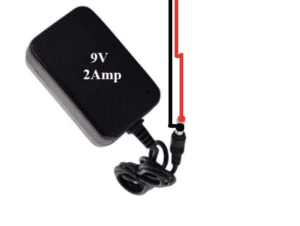
7 | 9v Power Supply | 1 |
Arduino Board
-
- The Arduino board is the control unit in the system.
- It is responsible for processing data, executing commands, and interacting with the GSM and GPS modules.
GSM Module (SIM800l)
-
- The GSM module facilitates communication with the vehicle using the Global System for Mobile Communications (GSM) network.
- It enables sending and receiving SMS messages, which allows for remote control and monitoring of the vehicle.
- The module is connected to the Arduino board to pin numbers 2 and 3.
GPS Module (NEO-6M)
-
- The GPS module integrates Global Positioning System (GPS) functionality into the tracking system.
- It receives signals from GPS satellites to determine the vehicle’s precise location coordinates.
- The module is connected to PINs 8 and 9.
LM2596 Step Down Conveter
Ignition Switch
-
- The ignition switch is a physical switch that controls the vehicle’s ignition system.
- It can be turned on or off remotely through SMS commands, providing control over the vehicle’s engine.
Relay Module Connection
Ignition Sensor
-
- The ignition sensor is an analog sensor connected to the Arduino board.
- It measures the voltage or resistance associated with the vehicle’s ignition status.
- The sensor helps detect whether the ignition is on or off, enabling the system to monitor the vehicle’s status.
Resistor (10Ω) and Resistor (10kΩ)
-
- These resistors are used in conjunction with the ignition sensor.
- They create a voltage divider circuit to convert the analog signal from the ignition sensor into a measurable value.
12V Power Supply
-
- The tracking system requires a 9V power supply to operate the Arduino board, GSM module, GPS module, and other components.
- The power supply can be sourced from the vehicle’s battery or an external power source.
Circuit Diagram
GSM Module
-
- RX pin of the GSM module is connected to digital pin 11 (txPin) of Arduino.
- TX pin of the GSM module is connected to digital pin 10 (rxPin) of Arduino.
- The GSM module is powered and grounded appropriately.
GPS Module
-
- RX pin of the GPS module is connected to digital pin 9 of Arduino (AltSoftSerial library is used).
- TX pin of the GPS module is connected to digital pin 8 of Arduino.
- The GPS module is powered and grounded appropriately.
Ignition Relay
-
- One terminal of the ignition Relay is connected to digital pin 4 of Arduino.
- The other terminal of the ignition switch is connected to the ground.
- A pull-up or pull-down resistor may be necessary based on the switch type.
Ignition Sensor
-
- The ignition sensor is connected to analog pin A0 of Arduino.
- Appropriate 1M and 100k resistors and wiring may be required for proper sensor connections.
Code
First Add All the Library and then upload the Code
AltSoftSerial
TinyGPS++

|
1 2 3 4 5 6 7 8 9 10 11 12 13 14 15 16 17 18 19 20 21 22 23 24 25 26 27 28 29 30 31 32 33 34 35 36 37 38 39 40 41 42 43 44 45 46 47 48 49 50 51 52 53 54 55 56 57 58 59 60 61 62 63 64 65 66 67 68 69 70 71 72 73 74 75 76 77 78 79 80 81 82 83 84 85 86 87 88 89 90 91 92 93 94 95 96 97 98 99 100 101 102 103 104 105 106 107 108 109 110 111 112 113 114 115 116 117 118 119 120 121 122 123 124 125 126 127 128 129 130 131 132 133 134 135 136 137 138 139 140 141 142 143 144 145 146 147 148 149 150 151 152 153 154 155 156 157 158 159 160 161 162 163 164 165 166 167 168 169 170 171 172 173 174 175 176 177 178 179 180 181 182 183 184 185 186 187 188 189 190 191 192 193 194 195 196 197 198 199 200 201 202 203 204 205 206 207 208 209 210 211 212 213 214 215 216 217 218 219 220 221 222 223 224 225 226 227 228 229 230 231 232 233 234 235 236 237 238 239 240 241 242 243 244 245 246 247 248 249 250 251 252 253 254 255 256 257 258 259 260 261 262 263 264 265 266 267 268 269 270 271 272 273 274 275 276 277 278 279 280 281 282 283 284 285 286 287 288 289 290 291 292 293 294 295 296 297 298 299 300 |
//Prateek //https://justdoelectronics.com //https://www.youtube.com/@JustDoElectronics #include <SoftwareSerial.h> #include <AltSoftSerial.h> #include <TinyGPS++.h> //sender phone number with country code const String PHONE = "+9188305848xx"; #define ignition_switch 4 #define ignition_sensor A0 //GSM Module RX pin to Arduino 11 //GSM Module TX pin to Arduino 10 #define rxPin 10 #define txPin 11 SoftwareSerial sim800(rxPin, txPin); //GPS Module RX pin to Arduino 9 //GPS Module TX pin to Arduino 8 AltSoftSerial neogps; TinyGPSPlus gps; String sms_status, sender_number, received_date, msg; boolean ignition_status = false; boolean tracking_status = false; boolean reply_status = true; boolean anti_theft = false; unsigned long previousMillis = 0; long interval = 60000; void setup() { delay(7000); Serial.begin(115200); sim800.begin(9600); neogps.begin(9600); pinMode(ignition_switch, OUTPUT); pinMode(ignition_sensor, INPUT); sms_status = ""; sender_number = ""; received_date = ""; msg = ""; sim800.println("AT"); delay(1000); sim800.println("ATE1"); delay(1000); sim800.println("AT+CPIN?"); delay(1000); sim800.println("AT+CMGF=1"); delay(1000); sim800.println("AT+CNMI=2,2,0,0,0"); delay(1000); } void loop() { ignition_status = getIgnitionStatus(); if (tracking_status == true && ignition_status == true) { unsigned long currentMillis = millis(); if (currentMillis - previousMillis > interval) { previousMillis = currentMillis; sendGpsToServer(); } } if (anti_theft == true && ignition_status == true) { digitalWrite(ignition_switch, HIGH); } while (sim800.available()) { parseData(sim800.readString()); } while (Serial.available()) { sim800.println(Serial.readString()); } } void parseData(String buff) { Serial.println(buff); unsigned int len, index; index = buff.indexOf("\r"); buff.remove(0, index + 2); buff.trim(); if (buff != "OK") { index = buff.indexOf(":"); String cmd = buff.substring(0, index); cmd.trim(); buff.remove(0, index + 2); if (cmd == "+CMTI") { index = buff.indexOf(","); String temp = buff.substring(index + 1, buff.length()); temp = "AT+CMGR=" + temp + "\r"; sim800.println(temp); } else if (cmd == "+CMGR") { extractSms(buff); if (sender_number == PHONE) { doAction(); } } } else { } } void extractSms(String buff) { unsigned int index; Serial.println(buff); index = buff.indexOf(","); sms_status = buff.substring(1, index - 1); buff.remove(0, index + 2); sender_number = buff.substring(0, 13); buff.remove(0, 19); received_date = buff.substring(0, 20); buff.remove(0, buff.indexOf("\r")); buff.trim(); index = buff.indexOf("\n\r"); buff = buff.substring(0, index); buff.trim(); msg = buff; buff = ""; msg.toLowerCase(); //Serial.println("----------------------------------"); //Serial.println(sms_status); //Serial.println(sender_number); //Serial.println(received_date); //Serial.println(msg); //Serial.println("----------------------------------"); } void doAction() { if (msg == "bike on") { digitalWrite(ignition_switch, HIGH); Serial.println("Bike has ON"); if (reply_status == true) { sendSms("Bike has ON"); } } else if (msg == "bike off") { digitalWrite(ignition_switch, LOW); Serial.println("Bike has OFF"); if (reply_status == true) { sendSms("Bike has OFF"); } } else if (msg == "get location") { sendSmsGPS("Location"); } else if (msg == "anti theft on") { anti_theft = true; if (reply_status == true) { sendSms("Someone Trying to start your bike"); sendSms("Bike Has OFF"); } } else if (msg == "anti theft off") { anti_theft = false; if (reply_status == true) { sendSms("Anti-Theft has OFF"); } else if (msg == "reply on") { reply_status = true; sendSms("Reply has ON"); } else if (msg == "reply off") { reply_status = false; } } else if (msg == "tracking on") { tracking_status = true; if (reply_status == true) { sendSms("Live Tracking has ON"); } } else if (msg == "tracking off") { tracking_status = false; if (reply_status == true) { sendSms("Live Tracking has OFF"); } } else if (msg == "tracking status") { if (tracking_status == false) { sendSms("Live Tracking has OFF"); } else { sendSms("Live Tracking has ON"); } } sms_status = ""; sender_number = ""; received_date = ""; msg = ""; } void deleteSms() { sendATcommand("AT+CMGD=1,4", "OK", 2000); Serial.println("All SMS are deleted."); } void sendSmsGPS(String text) { boolean newData = false; for (unsigned long start = millis(); millis() - start < 2000;) { while (neogps.available()) { if (gps.encode(neogps.read())) { newData = true; } } } if (newData) { float flat, flon; unsigned long age; Serial.print("Latitude= "); Serial.print(gps.location.lat(), 6); Serial.print(" Longitude= "); Serial.println(gps.location.lng(), 6); newData = false; delay(300); ///* sim800.print("AT+CMGF=1\r"); delay(1000); sim800.print("AT+CMGS=\"" + PHONE + "\"\r"); delay(1000); sim800.print("http://maps.google.com/maps?q=loc:"); sim800.print(gps.location.lat(), 6); sim800.print(","); sim800.print(gps.location.lng(), 6); delay(100); sim800.write(0x1A); delay(1000); Serial.println("GPS Message Sent Successfully."); } } void sendSms(String text) { sim800.print("AT+CMGF=1\r"); delay(1000); sim800.print("AT+CMGS=\"" + PHONE + "\"\r"); delay(1000); sim800.print(text); delay(100); sim800.write(0x1A); delay(1000); Serial.println("SMS Sent Successfully."); } int8_t sendATcommand(char* ATcommand, char* expected_answer, unsigned int timeout) { uint8_t x = 0, answer = 0; char response[100]; unsigned long previous; memset(response, '\0', 100); delay(100); while (sim800.available() > 0) sim800.read(); if (ATcommand[0] != '\0') { sim800.println(ATcommand); } x = 0; previous = millis(); do { if (sim800.available() != 0) { response[x] = sim800.read(); x++; if (strstr(response, expected_answer) != NULL) { answer = 1; } } } while ((answer == 0) && ((millis() - previous) < timeout)); return answer; } boolean getIgnitionStatus() { float val = 0; for (int i = 1; i <= 10; i++) { val = val + analogRead(ignition_sensor); } val = val / 10; if (val > 90) { return true; } else if (val < 50) { return false; } } void setIgnition() { ignition_status = getIgnitionStatus; if (ignition_status == false) { sim800.print("AT"); sendATcommand("AT+CSCLK=0", "OK", 1000); } else if (ignition_status == true) { sendATcommand("AT+CSCLK=2", "OK", 1000); } } int sendGpsToServer() { } |
After uploading the code open the serial monitor.
Video
Conclusion
Here we make the real-time location information tracker, and also we sensor notifications to vehicle owners if anything happens. This is used in various fields but in this article, we only show the Vehicle Location Tracking System.


