IoT Based Patient Health Monitoring System Using ESP32 And Blynk App
Monitoring Temperature, SpO2 And BPM Using Blynk App
Introduction
The Internet of Things technology has led to the development of various innovative solutions for healthcare. In this article, we will explore the creation of a Health Monitoring System using the Blynk App, ESP32 Board, MAX30100 Sensor, DHT11 Sensor, and DS18B20 Sensor. This system allows individuals to monitor their vital signs and environmental conditions in real-time, providing valuable insights for personal health management.
Circuit Components
S.N | Components | Quantity | Link To Buy |
1 | ESP32 Board | 1 | |
2 | MAX30100 Sensor | 1 | |
3 | DHT11 Sensor | 1 | |
4 | 4.7Kohm | 1 | |
5 | 5v Power Supply | 1 | |
6 | Zero PCB | 1 |
ESP32 Board
- ESP32 is a popular microcontroller board that is based on the ESP32 system-on-chip (SoC) developed by Espressif Systems.
- The ESP32 board includes a dual-core processor, built-in Wi-Fi and Bluetooth connectivity, making it suitable for a wide range of projects.
-
-
- Microcontroller- 32-bit Xtensa LX6 dual-core processor, which operates at a clock speed of up to 240 MHz. The dual-core architecture allows for multitasking tasks.
Features
- Memory: 520Kb SRAM
- WiFi: 802.11/g/n/e/i
- Bluetooth: v4.2 BR/EDR And BLE
- CPU: Xtensa Dual-core(or Single-core) 32-bit LX6 Microprocessor, Operating at 160 or 240 MHz And Performing at up to 600 DMIPS
- 10 × touch sensors
- Hall sensor
- LED PWM up to 16 channels
- Ultra-low Power (ULP) Co-Processor
- 12-Bit SAR ADC up to 18 channels
-
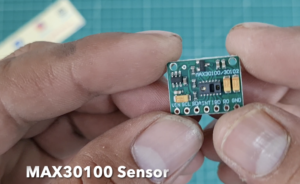
MAX30100 Sensor
- The MAX30100 sensor is a compact and versatile integrated module that combines two key functionalities.
- This sensor is commonly used for measuring heart rate and blood oxygen saturation levels (SpO2).
MAX30100 sensor used in, fitness trackers, and medical instruments.
Principle of Operation
-
- Oxygenated and deoxygenated blood absorb different amounts of light, allowing the sensor to determine the heart rate and estimate the oxygen saturation levels.
Features and Specifications
-
- The MAX30100 sensor is a highly integrated module that contains the necessary components for PPG measurements in a small form factor.
- It offers adjustable LED current and sampling rates, allowing flexibility in optimizing the measurements for different applications.
- The sensor provides digital output data in a standard I2C (Inter-Integrated Circuit) format, making it compatible with various microcontrollers and development boards.
- It operates on low power consumption, making it suitable for battery-powered devices.
- The MAX30100 sensor can be used in both stationary and motion-based scenarios due to its built-in motion artefact rejection algorithms.
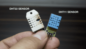
DHT11 Sensor
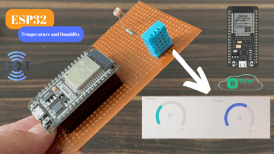
DHT11 sensor is a widely used digital temperature and humidity sensor in various projects. The sensor is small in size and can be easily integrated into any Microcontroller.
Principle of Operation
-
- The DHT11 sensor utilizes a capacitive humidity sensor and a thermistor to measure humidity and temperature, respectively.
- The humidity sensor consists of two electrodes with a moisture-absorbing material in between the electrical capacitance changes with the amount of moisture in the air.
- The thermistor is a type of resistor that varies its resistance with temperature changes.
- The sensor’s internal circuitry converts the analog readings from the humidity and temperature sensors into digital values for easy processing.
Features and Specifications
-
- The DHT11 sensor is a compact module with a built-in sensor element and signal-processing circuitry.
- It has a measurement range of 20-90% relative humidity with an accuracy of ±5%.
- The temperature measurement range is 0-50°C with an accuracy of ±2°C.
- The sensor operates on a supply voltage of 3.3-5V, making it compatible with various microcontrollers and development boards.
Circuit Diagram
ESP32 Board
- Connect the VIN pin of the ESP32 board to a 3.3V power supply.
- Connect the GND pin of the ESP32 board to the ground.
- Connect the SDA pin of the ESP32 board to the SDA pin of the MAX30100 sensor.
- Connect the SCL pin of the ESP32 board to the SCL pin of the MAX30100 sensor.
MAX30100 Sensor
- Connect the VCC pin of the MAX30100 sensor to a 3.3V power supply.
- Connect the GND pin of the MAX30100 sensor to the ground.
- Connect the SDA pin of the MAX30100 sensor to the SDA(21) pin of the ESP32 board.
- Connect the SCL pin of the MAX30100 sensor to the SCL(22) pin of the ESP32 board.
DHT11 Sensor
- Connect the VCC pin of the DHT11 sensor to a 3.3V power supply.
- Connect the GND pin of the DHT11 sensor to the ground.
- Connect the data pin (out) of the DHT11 sensor to a digital pin on the ESP32 board (D18).
DS18B20 Sensor
- Connect the VCC pin of the DS18B20 sensor to a 3.3V power supply.
- Connect the GND pin of the DS18B20 sensor to the ground.
- Connect the data pin of the DS18B20 sensor to a digital pin on the ESP32 board (D5).
Additionally, you’ll need to connect the ESP32 board to Wi-Fi for communication with the Blynk App. Ensure that you have a stable Wi-Fi connection and provide the correct Wi-Fi credentials in your code.
Blynk App Setup
Download and Install the Blynk App
- Download the Blynk app from the App Store (iOS) or Google Play Store (Android).
- Install the app on your smartphone or tablet.
Create a New Blynk Project
- Open the Blynk app and create a new account or log in if you already have one.
- Tap on the “Create New Project” button.
- Give your project a name (e.g., Health Monitoring System).
- Select the ESP32 board as the device.
- Choose the appropriate connection type (Wi-Fi).
Obtain the Authentication Token
- After creating the project, you’ll receive an email containing the authentication token.
- Check your email and copy the authentication token.
Set up the Blynk App Interface
- Open the Blynk app and go to your project.
- Tap on the “+” icon to add a widget.
- Choose the appropriate widget type for each of the following parameters:
- Temperature: Select the Value Display widget and assign it to Virtual Pin V3.
- Humidity: Select the Value Display widget and assign it to Virtual Pin V4.
- Heart Rate: Select the Value Display widget and assign it to Virtual Pin V5.
- SpO2: Select the Value Display widget and assign it to Virtual Pin V6.
- Body Temperature: Select the Value Display widget and assign it to Virtual Pin V7.
- Customize the appearance and settings of the widgets as desired.
Update the Code with the Blynk Authentication Token
- In the Arduino code, locate the line:
char auth[] = "G9nCH4W7AWUwviplzwpGLleH0fOdXF9_";.
Connect the ESP32 Board to the Blynk App
- Make sure your smartphone or tablet is connected to the same Wi-Fi network as your ESP32 board.
- Upload the modified code to your ESP32 board.
- Open the Serial Monitor in the Arduino IDE to monitor the board’s status.
- Once the ESP32 board is powered on and connected to Wi-Fi, it will establish a connection with the Blynk server. The Serial Monitor will display the connection status.
- If the connection is successful, the board will start sending sensor data to the Blynk app.
Monitor Sensor Readings on the Blynk App
- Go back to the Blynk app and ensure you are on your project’s screen.
- You should see the sensor readings (temperature, humidity, heart rate, SpO2, and body temperature) displayed on their respective widgets.
Source Code
|
1 2 3 4 5 6 7 8 9 10 11 12 13 14 15 16 17 18 19 20 21 22 23 24 25 26 27 28 29 30 31 32 33 34 35 36 37 38 39 40 41 42 43 44 45 46 47 48 49 50 51 52 53 54 55 56 57 58 59 60 61 62 63 64 65 66 67 68 69 70 71 72 73 74 75 76 77 78 79 80 81 82 83 84 85 86 87 88 89 |
//Prateek //https://justdoelectronics.com //https://www.youtube.com/c/JustDoElectronics/videos #include <Wire.h> #include "MAX30100_PulseOximeter.h" #define BLYNK_PRINT Serial #include <Blynk.h> #include <WiFi.h> #include <BlynkSimpleEsp32.h> #include <OneWire.h> #include <DallasTemperature.h> #include "DHT.h" #define DHTTYPE DHT11 #define REPORTING_PERIOD_MS 1000 #define DS18B20 5 char auth[] = "G9nCH4W7AWUwviplzwpGLleH0fOdXF9_"; char ssid[] = "justdoelectronics"; char pass[] = "123456789"; PulseOximeter pox; uint8_t DHTPin = 18; DHT dht(DHTPin, DHTTYPE); float Temperature; float Humidity; float bodytemperature; float BPM, SpO2; uint32_t tsLastReport = 0; OneWire oneWire(DS18B20); DallasTemperature sensors(&oneWire); void onBeatDetected() { Serial.println("Beat Detected!"); } void setup() { Serial.begin(115200); pinMode(19, OUTPUT); pinMode(DHTPin, INPUT); dht.begin(); Blynk.begin(auth, ssid, pass); Serial.print("Initializing Pulse Oximeter.."); if (!pox.begin()) { Serial.println("FAILED"); for (;;) ; } else { Serial.println("SUCCESS"); pox.setOnBeatDetectedCallback(onBeatDetected); } pox.setIRLedCurrent(MAX30100_LED_CURR_7_6MA); } void loop() { pox.update(); Blynk.run(); Temperature = dht.readTemperature(); Humidity = dht.readHumidity(); BPM = pox.getHeartRate(); SpO2 = pox.getSpO2(); bodytemperature = sensors.getTempCByIndex(0); if (millis() - tsLastReport > REPORTING_PERIOD_MS) { Serial.print("Heart rate:"); Serial.print(BPM); Serial.print(" bpm / SpO2:"); Serial.print(SpO2); Serial.println(" %"); Serial.print("Room Temperature: "); Serial.print(Temperature); Serial.println("°C"); Serial.print("Room Humidity: "); Serial.print(Humidity); Serial.println("%"); Serial.print("Body Temperature: "); Serial.print(bodytemperature); Serial.println("°C"); Blynk.virtualWrite(V3, Temperature); Blynk.virtualWrite(V4, Humidity); Blynk.virtualWrite(V5, BPM); Blynk.virtualWrite(V6, SpO2); Blynk.virtualWrite(V7, bodytemperature); tsLastReport = millis(); } } |
Setup()
-
- The setup() function is executed once when the microcontroller starts.
- Serial communication is initiated at a baud rate of 115200 for debugging purposes.
|
1 2 3 4 5 6 7 8 9 10 11 12 13 14 15 16 17 18 |
void setup() { Serial.begin(115200); pinMode(19, OUTPUT); pinMode(DHTPin, INPUT); dht.begin(); Blynk.begin(auth, ssid, pass); Serial.print("Initializing Pulse Oximeter.."); if (!pox.begin()) { Serial.println("FAILED"); for (;;) ; } else { Serial.println("SUCCESS"); pox.setOnBeatDetectedCallback(onBeatDetected); } pox.setIRLedCurrent(MAX30100_LED_CURR_7_6MA); } |
Loop()
-
- The loop() function continuously runs after the setup() function.
- The pox. update() function is called to update the readings from the MAX30100 sensor.
- The Blynk. run() function is called to maintain the connection and handle Blynk-related operations.
|
1 2 3 4 5 6 7 8 9 10 11 12 13 14 15 16 17 18 19 20 21 22 23 24 25 26 27 28 29 30 31 32 33 |
void loop() { pox.update(); Blynk.run(); Temperature = dht.readTemperature(); Humidity = dht.readHumidity(); BPM = pox.getHeartRate(); SpO2 = pox.getSpO2(); bodytemperature = sensors.getTempCByIndex(0); if (millis() - tsLastReport > REPORTING_PERIOD_MS) { Serial.print("Heart rate:"); Serial.print(BPM); Serial.print(" bpm / SpO2:"); Serial.print(SpO2); Serial.println(" %"); Serial.print("Room Temperature: "); Serial.print(Temperature); Serial.println("°C"); Serial.print("Room Humidity: "); Serial.print(Humidity); Serial.println("%"); Serial.print("Body Temperature: "); Serial.print(bodytemperature); Serial.println("°C"); Blynk.virtualWrite(V3, Temperature); Blynk.virtualWrite(V4, Humidity); Blynk.virtualWrite(V5, BPM); Blynk.virtualWrite(V6, SpO2); Blynk.virtualWrite(V7, bodytemperature); tsLastReport = millis(); } } |
Video
Conclusion
It empowers individuals to take control of their health by providing instant access to vital sign data and environmental conditions. By leveraging IoT technology, this system has the potential to revolutionize personal healthcare management and enhance overall well-being.
ESP32 Related Projects

