Introduction
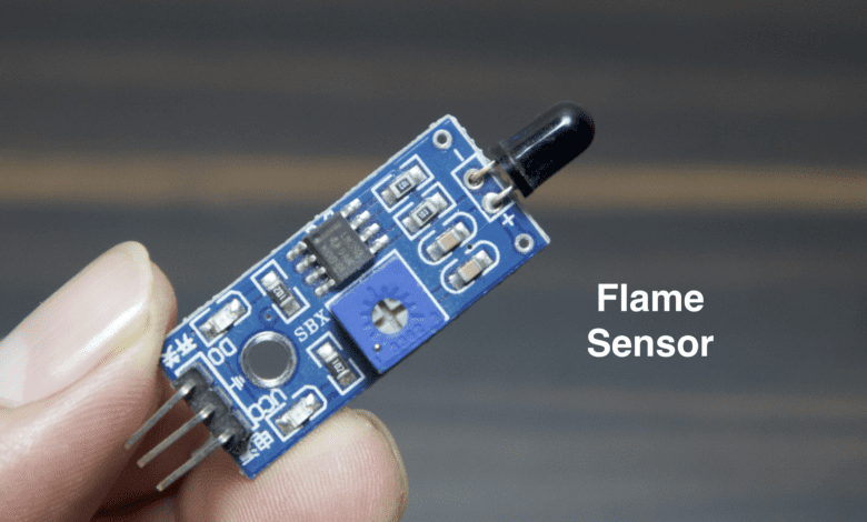
In This Article, we explain how the flame sensor works and interfaces with any microcontroller. the flame sensor is available in digital and analog form and it detects fire. here we interfacing the flame sensor with Arduino, ESp8266 and ESP32 microcontroller.
The flame sensor operating voltage is required only 5v and is logic output is digital from logic high and logic Low. When the fire is detected the sensor goes logic low and is not fire detected the output is logic high.
- Here is the circuit diagram of the flame sensor we take reference from a flame sensor datasheet.
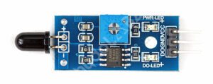
- The Flame sensor used the IC LM393 and is also connected to the two indicators LED when the sensor detects any fire the red led will glow and is not detected any fire the green led glows also set your threshold value with the help of 10k pot.
- They used IR photodiodes or phototransistors to detect the sensitive infrared light.
Working Principle of Flame Sensor
The working flame sensor, at the top, is a photodiode available and is detected the fire. if the fire is detected the photodiode anode pin is high and is given to the signal of LM393 IC.
If the fire is detected The Digital value is LOW(0v) and if not detected any fire the output value is HIGH(5v).and the output pin is connected to any digital pin of a microcontroller like Arduino.
- The flame sensor is 3 Terminal Sensor VCC, GND and OUTPUT.
- the flame sensor is also in board 10k variable resister they set the sensitive value.
Specifications of the Flame Sensor
- Sensing Range: Few centimetres up to several meters.
- Detection Angle: Narrow angles such as 60 degrees or 90 degrees.
- Response Time: Few milliseconds to several seconds.
- Operating Voltage: The Voltage ranges from 3.3V, 5V, or 12V, depending on the sensor.
- Output Type: Digital or Analog.
Advantages of the Flame Sensor
- Early Fire Detection
- Reliable Flame Detection
- Fast Response Time
- Versatile Applications
Disadvantage of the Flame Sensor
- Limited to Flame Detection
- False Alarms
- Environmental Factors
Application of the Flame Sensor
- Fire Alarm Systems
- Industrial Furnaces and Boilers
- Gas Appliances
- Automotive Safety Systems
- Industrial Process Control
- Aircraft Fire Detection
Example with Arduino
Now we interface the flame sensor with Arduino Uno Board and the value will display the serial monitor as well as LCD Display.
- We connected the flame sensor to digital pin number 10.
- The LCD Will be connected to the pin number (2,3,4,5,6,7).
- we used the buzzer for indication and is connected to pin number 11.
Circuit Diagram
Code With Serial Monitor
|
1 2 3 4 5 6 7 8 9 10 11 12 13 14 15 16 17 18 19 20 |
int LED = 13; int isFlamePin = 10; int isFlame = HIGH; void setup() { pinMode(LED, OUTPUT); pinMode(isFlamePin, INPUT); Serial.begin(9600); } void loop() { isFlame = digitalRead(isFlamePin); if (isFlame == LOW) { Serial.println("FLAME ...."); digitalWrite(LED, HIGH); } else { Serial.println("NO FFLAME.."); digitalWrite(LED, LOW); } } |
Code with 16×2 LCD Display
|
1 2 3 4 5 6 7 8 9 10 11 12 13 14 15 16 17 18 19 20 21 22 23 24 25 26 27 28 29 30 31 32 33 34 35 36 37 38 39 40 41 42 43 44 45 46 47 48 49 50 51 52 53 54 55 56 57 58 59 |
#include <LiquidCrystal.h> LiquidCrystal lcd(2, 3, 4, 5, 6, 7); #define flamePin 10 #define buzzerPin 11 void setup() { Serial.begin(9600); lcd.begin(16, 2); pinMode(buzzerPin,OUTPUT); pinMode(flamePin,INPUT); lcd.setCursor(0, 0); lcd.print(“Calibrating”); for(int i = 0; i <15; i++){ if (i==4) { lcd.setCursor(0, 1); lcd.print(“.”); } else lcd.print(“.”); delay(500); } lcd.setCursor(11, 1); lcd.print(“Done”); delay(1000); lcd.clear(); lcd.setCursor(1, 0); lcd.print(“Sensor Active”); delay(1500); lcd.clear(); } void loop() { int Flame = digitalRead(flamePin); if (Flame == LOW) { digitalWrite(buzzerPin,HIGH); lcd.setCursor(0, 0); lcd.print(“ Flame : “); lcd.print(“Flame”); lcd.setCursor(0, 1); lcd.print(“ is Detected”); Serial.print(Flame); Serial.print(“\t”); Serial.print(“Flame is Detected”); } else if (Flame == HIGH) { digitalWrite(buzzerPin,LOW); lcd.setCursor(0, 0); lcd.print(“Flame : “); lcd.print(“No Flame”); Serial.print(Flame); Serial.print(“\t”); Serial.println(“No Flame”); } delay(300); lcd.clear(); } |
Fire Alarm System Using GSM And Arduino
Circuit Diagram
Code
|
1 2 3 4 5 6 7 8 9 10 11 12 13 14 15 16 17 18 19 20 21 22 23 24 25 26 27 28 29 30 31 32 33 34 35 36 37 38 39 40 41 42 43 44 45 46 47 48 49 50 51 52 |
#include <LiquidCrystal_I2C.h> LiquidCrystal_I2C lcd(0x27, 16, 2); int sensorPin = 6; int buzzer = 4; int green = 5; int red = 3; int read_value; void setup() { pinMode(sensorPin, INPUT); pinMode(buzzer, OUTPUT); pinMode(red, OUTPUT); pinMode(green, OUTPUT); lcd.init(); lcd.backlight(); lcd.begin(16, 2); lcd.clear(); lcd.setCursor(0, 0); lcd.print(" WELCOME To "); lcd.setCursor(0, 1); lcd.print(" Fire Detector "); delay(2000); lcd.clear(); } void loop() { read_value = digitalRead(sensorPin); if (read_value == 1) { lcd.setCursor(0, 0); lcd.print(" Not Flame "); lcd.setCursor(0, 1); lcd.print(".....Normal....."); digitalWrite(buzzer, LOW); digitalWrite(red, LOW); digitalWrite(green, HIGH); } else { lcd.setCursor(0, 0); lcd.print("Fire is Detected"); lcd.setCursor(0, 1); lcd.print("Alert....... "); digitalWrite(buzzer, HIGH); digitalWrite(red, HIGH); digitalWrite(green, LOW); delay(1000); } delay(100); } |
Fire And Smoke Detector Using Arduino
Circuit Diagram
Code
Videos
Conclusion
Flame sensors are essential components in fire safety systems and various industrial applications where the detection of flames is critical. They provide reliable and fast flame detection, allowing for timely response and appropriate safety measures to be taken.
Sensor
