Attendance System Using EM-18 Module,GSM Module And Arduino
attendance system arduino
Introduction
In this article, we will guide you through the process of creating an attendance system using an Arduino Nano microcontroller board. The system will utilize various components including a 16×2 LCD display with an I2C interface, an EM-18 module for RFID scanning, an LM2596 voltage regulator, and a GSM SIM800L module for sending attendance data via SMS. This system will provide a convenient and efficient way to track attendance in various settings such as schools, offices, or events.
Components Needed
- Arduino Nano
- EM-18 RFID Module
- 16×2 LCD Display with I2C
- GSM sim800l Module
- LM2596 Step Down Conveter
- Wire
- Zero PCB
- 9V power supply
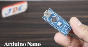
Arduino Nano
The Arduino Nano is a compact and versatile development board based on the ATmega328P microcontroller. It is similar to the Arduino Uno but comes in a smaller form factor, making it suitable for projects with space constraints.
Microcontroller
-
- The Arduino Nano is built around the ATmega328P microcontroller from Atmel (now Microchip). It is an 8-bit microcontroller with 32KB of flash memory, 2KB of SRAM, and 1KB of EEPROM.
Board Layout and Pins
-
- The Arduino Nano features a small rectangular board with two rows of pin headers along the sides for connecting to external components and peripherals.
- It typically has 14 digital input/output (I/O) pins, 8 analog input pins, UART (serial communication) pins, I2C and SPI pins, power pins, and other auxiliary pins.
- Some variations of the Arduino Nano also include additional features like integrated USB connectivity or built-in sensors.
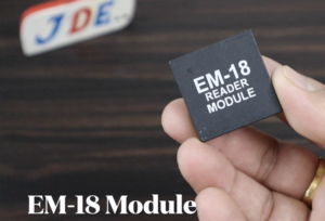
EM-18 RFID Module
The EM-18 RFID (Radio Frequency Identification) module is a compact and cost-effective RFID reader module widely used for various applications. It allows for easy integration of RFID functionality into projects requiring identification and tracking capabilities.
RFID Technology
-
- RFID is a technology that uses electromagnetic fields to wirelessly identify and track tags or cards that contain electronically stored information.
- The EM-18 RFID module is specifically designed to work with EM4100 family RFID tags, which operate at a frequency of 125kHz.
Hardware Components
-
- The EM-18 RFID module consists of an antenna coil, control circuitry, and necessary support components, all integrated into a compact module.
- It typically has three pins for connection: VCC (power supply), GND (ground), and DATA (data output).
Operating Principle
-
- When an RFID tag is brought into the proximity of the EM-18 RFID module, the module emits a low-frequency electromagnetic field.
- The RFID tag receives power from this field and sends back its unique identification information to the module.
- The module reads this information and outputs it through the DATA pin.
Data Output
-
- The EM-18 RFID module uses a simple 9600 baud serial communication protocol to output the data read from the RFID tag.
- The DATA pin of the module is connected to a microcontroller or other serial-enabled device to receive the RFID tag data.
- The data is usually transmitted as a string of characters or hexadecimal values representing the tag’s unique identification number.
16×2 LCD Display with I2C
A 16×2 LCD display with I2C (Inter-Integrated Circuit) is a popular combination for displaying information in Arduino and other microcontroller projects. It combines a 16-character by 2-line liquid crystal display (LCD) module with an I2C backpack module, which simplifies the connection and control of the display.
LCD Display
-
- The LCD module consists of a monochrome display panel with 16 columns and 2 rows, allowing for a total of 32 characters to be displayed.
- Each character position can display alphanumeric characters, symbols, or custom-defined characters.
- The display is typically backlit, with options for different backlight colours such as blue, green, yellow, or white.
I2C Backpack
-
- The I2C backpack is an additional module that attaches to the back of the LCD display module.
- It incorporates an I2C communication interface, which allows for easy and efficient communication between the display and the microcontroller.
- The backpack module includes an I2C-to-parallel converter chip (such as PCF8574) that reduces the number of I/O pins required for controlling the LCD display.
I2C Communication
-
- I2C is a serial communication protocol that enables data transfer between integrated circuits using two signal lines: SDA (data line) and SCL (clock line).
- The I2C backpack module acts as an interface between the microcontroller and the LCD display, translating the commands and data received via I2C to the appropriate signals for the display.
Simplified Connection
-
- The I2C backpack significantly reduces the number of wires required to connect the LCD display to the microcontroller.
- Instead of using multiple digital pins for data and control signals, the I2C backpack only requires two wires (SDA and SCL) for communication with the microcontroller.
- This simplifies the wiring and frees up additional digital pins on the microcontroller for other purposes.
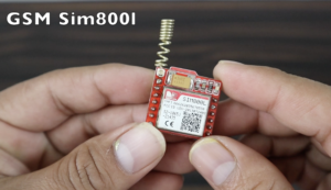
GSM sim800l Module
The GSM SIM800L module is a compact and affordable module that allows communication over the Global System for Mobile Communications (GSM) network. It enables devices to connect to the internet, send and receive SMS messages, make phone calls, and perform various other tasks.
- The GSM SIM800L module is a small-sized module that can be easily integrated into various projects.
- It typically operates on low voltage (3.4V to 4.4V) and requires a stable power supply.
- The module includes various interface pins for power supply, UART communication, antenna connection, and other control signals.
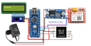
Circuit Diagram
Arduino Nano and 16×2 LCD Display
-
- Connect the VCC pin of the LCD display to the 5V pin on the Arduino Nano.
- Connect the GND pin of the LCD display to the GND pin on the Arduino Nano.
- Connect the SDA pin of the LCD display to the A4/SDA pin on the Arduino Nano.
- Connect the SCL pin of the LCD display to the A5/SCL pin on the Arduino Nano.
Arduino Nano and EM-18 Module
-
- Connect the VCC pin of the EM-18 module to the 5V pin on the Arduino Nano.
- Connect the GND pin of the EM-18 module to the GND pin on the Arduino Nano.
- Connect the TX pin of the EM-18 module to the RX pin on the Arduino Nano.
Arduino Nano and LM2596
-
- Connect the VIN pin of the LM2596 to the 9V pin on the Arduino Nano.
- Connect the GND pin of the LM2596 to the GND pin on the Arduino Nano.
Arduino Nano and GSM SIM800L Module
-
- Connect the VCC pin of the GSM SIM800L module to the 3.7V pin on the Arduino Nano.
- Connect the GND pin of the GSM SIM800L module to the GND pin on the Arduino Nano.
- Connect the TX pin of the GSM SIM800L module to the D2 pin on the Arduino Nano.
- Connect the RX pin of the GSM SIM800L module to the D3 pin on the Arduino Nano.
Source Code
|
1 2 3 4 5 6 7 8 9 10 11 12 13 14 15 16 17 18 19 20 21 22 23 24 25 26 27 28 29 30 31 32 33 34 35 36 37 38 39 40 41 42 43 44 45 46 47 48 49 50 51 52 53 54 55 56 57 58 59 60 61 62 63 64 65 66 67 68 69 70 71 72 73 74 75 76 77 78 79 80 81 82 83 84 85 86 87 88 89 90 91 92 93 94 95 96 97 98 99 100 101 102 103 104 105 106 107 108 109 110 111 112 113 114 115 116 117 118 119 120 121 122 123 124 125 126 127 128 129 130 131 132 133 134 135 136 137 138 139 140 141 142 143 144 145 146 147 148 149 150 151 152 153 154 155 156 157 158 159 160 161 162 163 164 165 166 167 168 169 170 171 172 173 174 175 176 177 178 179 180 181 182 183 184 185 186 187 188 189 190 191 192 193 194 195 196 197 198 199 200 201 202 203 204 205 206 207 208 209 210 211 212 |
//Prateek //https://justdoelectronics.com //https://www.youtube.com/c/JustDoElectronics/videos #include <SoftwareSerial.h> #include <LiquidCrystal_I2C.h> LiquidCrystal_I2C lcd(0x27, 16, 2); SoftwareSerial sim(3, 2); String number = "+9188305848xx"; String number1 = "+9188305848xx"; String number2 = "+91"; String number3 = "+91"; String number4 = "+91"; int state1 = 0; int state2 = 0; int state3 = 0; int state4 = 0; int state5 = 0; #define buzzerPin 4 #define yellow 5 #define green 6 String page = ""; char input[12]; int count = 0; int a; double total = 0; int count_prod = 0; void setup() { lcd.init(); lcd.backlight(); lcd.setCursor(0, 0); Serial.begin(9600); sim.begin(9600); pinMode(buzzerPin, OUTPUT); pinMode(yellow, OUTPUT); pinMode(green, OUTPUT); lcd.setCursor(0, 0); lcd.print(" WELCOME "); lcd.setCursor(0, 1); lcd.print("TO OUR PROJECT"); delay(4000); lcd.clear(); } void loop() { rfid(); } void rfid() { if (Serial.available()) { count = 0; while (Serial.available() && count < 12) { input[count] = Serial.read(); count++; delay(5); } if (count == 12) { if ((strncmp(input, "03007BFA20A2", 12) == 0) && (state1 == 0)) { beepON(); digitalWrite(green, HIGH); delay(2000); digitalWrite(green, LOW); lcd.clear(); lcd.setCursor(7, 0); lcd.print("Prateek"); lcd.setCursor(11, 1); lcd.print("001"); info(); SendPrateek(); state1 = 1; } else if ((strncmp(input, "03007BFA20A2", 12) == 0) && (state1 == 1)) { beepON(); digitalWrite(yellow, HIGH); delay(2000); digitalWrite(yellow, LOW); lcd.clear(); lcd.setCursor(7, 0); lcd.print("Prateek"); lcd.setCursor(11, 1); lcd.print("001"); info(); SendPrateek(); state1 = 0; } else if ((strncmp(input, "03007C2DA0F2", 12) == 0) && (state1 == 0)) { beepON(); digitalWrite(green, HIGH); delay(2000); digitalWrite(green, LOW); lcd.clear(); lcd.setCursor(7, 0); lcd.print("Sonu"); lcd.setCursor(11, 1); lcd.print("002"); info(); SendSonu(); state2 = 1; } else if ((strncmp(input, "03007C2DA0F2", 12) == 0) && (state1 == 1)) { beepON(); digitalWrite(yellow, HIGH); delay(2000); digitalWrite(yellow, LOW); lcd.clear(); lcd.setCursor(7, 0); lcd.print("Sonu"); lcd.setCursor(11, 1); lcd.print("002"); info(); SendSonu(); state2 = 0; } else if ((strncmp(input, "03007C8531CB", 12) == 0) && (state1 == 0)) { beepON(); digitalWrite(green, HIGH); delay(2000); digitalWrite(green, LOW); lcd.clear(); lcd.setCursor(7, 0); lcd.print("Punit"); lcd.setCursor(11, 1); lcd.print("003"); info(); SendPunit(); state3 = 1; } else if ((strncmp(input, "03007C8531CB", 12) == 0) && (state1 == 1)) { beepON(); digitalWrite(yellow, HIGH); delay(2000); digitalWrite(yellow, LOW); lcd.clear(); lcd.setCursor(7, 0); lcd.print("Punit"); lcd.setCursor(11, 1); lcd.print("003"); info(); SendPunit(); state3 = 0; } else if ((strncmp(input, "03007CBE41B0", 12) == 0) && (state1 == 0)) { beepON(); digitalWrite(green, HIGH); delay(2000); digitalWrite(green, LOW); lcd.clear(); lcd.setCursor(7, 0); lcd.print("Ram"); lcd.setCursor(11, 1); lcd.print("004"); info(); SendRam(); state4 = 1; } else if ((strncmp(input, "03007CBE41B0", 12) == 0) && (state1 == 1)) { beepON(); digitalWrite(yellow, HIGH); delay(2000); digitalWrite(yellow, LOW); lcd.clear(); lcd.setCursor(7, 0); lcd.print("Ram"); lcd.setCursor(11, 1); lcd.print("003"); info(); SendRam(); state3 = 0; } else { digitalWrite(buzzerPin, HIGH); lcd.clear(); lcd.setCursor(0, 0); lcd.print("ID : "); lcd.print("Unknown"); lcd.setCursor(0, 1); lcd.print("Access denied"); Serial.println(" Access denied"); delay(1500); digitalWrite(buzzerPin, LOW); lcd.clear(); } } } } void smsSend() { lcd.setCursor(0, 0); lcd.print("SMS Sending"); for (int x = 11; x < 16; x++) { lcd.setCursor(x, 0); lcd.print("."); delay(1000); lcd.clear(); } } void beepON() { digitalWrite(buzzerPin, HIGH); delay(200); digitalWrite(buzzerPin, LOW); delay(100); } void info() { lcd.setCursor(0, 0); lcd.print("Name : "); lcd.setCursor(0, 1); lcd.print("Roll No : "); delay(1500); lcd.clear(); lcd.setCursor(0, 0); lcd.print("Authorized Access"); delay(1000); lcd.clear(); } |
Libraries
-
- The code uses two libraries:
SoftwareSerialandLiquidCrystal_I2C.SoftwareSerialis used to create a software serial connection for communicating with the SIM module, whileLiquidCrystal_I2Cis used to control a 16×2 LCD display using I2C communication.
- The code uses two libraries:
|
1 2 |
#include <SoftwareSerial.h> #include <LiquidCrystal_I2C.h> |
Pin Definitions
-
- The code defines the pin assignments for the buzzer (
buzzerPin), yellow LED (yellow), and green LED (green).
- The code defines the pin assignments for the buzzer (
|
1 2 3 4 |
SoftwareSerial sim(3, 2); #define buzzerPin 4 #define yellow 5 #define green 6 |
Variable Declarations
-
- Various variables are declared to store RFID tag numbers, states, and other values used in the program.
number,number1,number2, andnumber3store phone numbers to which SMS messages will be sent.state1,state2,state3, andstate4represent the states of different individuals.pageis a string variable used to store web page data?inputis a character array used to store RFID tag data received from the reader?countkeeps track of the number of characters received from the RFID reader.
|
1 2 3 4 5 6 7 8 9 10 |
String number = "+9188305848xx"; String number1 = "+9188305848xx"; String number2 = "+91"; String number3 = "+91"; String number4 = "+91"; int state1 = 0; int state2 = 0; int state3 = 0; int state4 = 0; int state5 = 0; |
setup() Function
-
- Initializes the LCD display, sets the baud rate for serial communication, and initializes the SIM module and pins.
- Displays a welcome message on the LCD for 4 seconds.
|
1 2 3 4 5 6 7 8 9 10 11 12 13 14 15 16 17 18 |
void setup() { lcd.init(); lcd.backlight(); lcd.setCursor(0, 0); Serial.begin(9600); sim.begin(9600); pinMode(buzzerPin, OUTPUT); pinMode(yellow, OUTPUT); pinMode(green, OUTPUT); lcd.setCursor(0, 0); lcd.print(" WELCOME "); lcd.setCursor(0, 1); lcd.print("TO OUR PROJECT"); delay(4000); lcd.clear(); } |
loop() Function
|
1 2 3 |
void loop() { rfid(); } |
- Calls the
rfid()function repeatedly. rfid()Function
|
1 2 3 4 5 6 7 8 9 10 11 12 13 14 15 16 17 18 19 20 21 22 23 24 25 26 27 28 29 30 31 32 33 34 35 36 37 38 39 40 41 42 43 44 45 46 47 48 49 50 51 52 53 54 55 56 57 58 59 60 61 62 63 64 65 66 67 68 69 70 71 72 73 74 75 76 77 78 79 80 81 82 83 84 85 86 87 88 89 90 91 92 93 94 95 96 97 98 99 100 101 102 103 104 105 106 107 108 109 110 111 112 113 114 115 116 117 118 119 120 121 122 123 124 125 126 127 128 129 130 131 |
void rfid() { if (Serial.available()) { count = 0; while (Serial.available() && count < 12) { input[count] = Serial.read(); count++; delay(5); } if (count == 12) { if ((strncmp(input, "03007BFA20A2", 12) == 0) && (state1 == 0)) { beepON(); digitalWrite(green, HIGH); delay(2000); digitalWrite(green, LOW); lcd.clear(); lcd.setCursor(7, 0); lcd.print("Prateek"); lcd.setCursor(11, 1); lcd.print("001"); info(); SendPrateek(); state1 = 1; } else if ((strncmp(input, "03007BFA20A2", 12) == 0) && (state1 == 1)) { beepON(); digitalWrite(yellow, HIGH); delay(2000); digitalWrite(yellow, LOW); lcd.clear(); lcd.setCursor(7, 0); lcd.print("Prateek"); lcd.setCursor(11, 1); lcd.print("001"); info(); SendPrateek(); state1 = 0; } else if ((strncmp(input, "03007C2DA0F2", 12) == 0) && (state1 == 0)) { beepON(); digitalWrite(green, HIGH); delay(2000); digitalWrite(green, LOW); lcd.clear(); lcd.setCursor(7, 0); lcd.print("Sonu"); lcd.setCursor(11, 1); lcd.print("002"); info(); SendSonu(); state2 = 1; } else if ((strncmp(input, "03007C2DA0F2", 12) == 0) && (state1 == 1)) { beepON(); digitalWrite(yellow, HIGH); delay(2000); digitalWrite(yellow, LOW); lcd.clear(); lcd.setCursor(7, 0); lcd.print("Sonu"); lcd.setCursor(11, 1); lcd.print("002"); info(); SendSonu(); state2 = 0; } else if ((strncmp(input, "03007C8531CB", 12) == 0) && (state1 == 0)) { beepON(); digitalWrite(green, HIGH); delay(2000); digitalWrite(green, LOW); lcd.clear(); lcd.setCursor(7, 0); lcd.print("Punit"); lcd.setCursor(11, 1); lcd.print("003"); info(); SendPunit(); state3 = 1; } else if ((strncmp(input, "03007C8531CB", 12) == 0) && (state1 == 1)) { beepON(); digitalWrite(yellow, HIGH); delay(2000); digitalWrite(yellow, LOW); lcd.clear(); lcd.setCursor(7, 0); lcd.print("Punit"); lcd.setCursor(11, 1); lcd.print("003"); info(); SendPunit(); state3 = 0; } else if ((strncmp(input, "03007CBE41B0", 12) == 0) && (state1 == 0)) { beepON(); digitalWrite(green, HIGH); delay(2000); digitalWrite(green, LOW); lcd.clear(); lcd.setCursor(7, 0); lcd.print("Ram"); lcd.setCursor(11, 1); lcd.print("004"); info(); SendRam(); state4 = 1; } else if ((strncmp(input, "03007CBE41B0", 12) == 0) && (state1 == 1)) { beepON(); digitalWrite(yellow, HIGH); delay(2000); digitalWrite(yellow, LOW); lcd.clear(); lcd.setCursor(7, 0); lcd.print("Ram"); lcd.setCursor(11, 1); lcd.print("003"); info(); SendRam(); state3 = 0; } else { digitalWrite(buzzerPin, HIGH); lcd.clear(); lcd.setCursor(0, 0); lcd.print("ID : "); lcd.print("Unknown"); lcd.setCursor(0, 1); lcd.print("Access denied"); Serial.println(" Access denied"); delay(1500); digitalWrite(buzzerPin, LOW); lcd.clear(); } } } } |
- Checks if there is data available from the RFID reader (Serial communication).
- If data is available, it reads the RFID tag number and stores it in the
inputarray. - It then compares the received tag number with predefined tag numbers to determine the user and their state.
- Based on the tag number and state, it performs the following actions:
- Turns on the buzzer, lights up the corresponding LED, and displays useful information on the LCD.
- Calls the
info()function to display an authorized access message. - Calls the respective
SendPrateek(),SendSonu(),SendPunit(), orSendRam()function to send an SMS message to the corresponding phone number. - If the received tag number does not match any predefined tags, it denies access, sounds the buzzer, and displays an access denied message.
SMS Sending Functions
-
- These functions are responsible for sending SMS messages using the SIM module.
- They set the SIM module to SMS text mode, specify the recipient’s phone number, and send the appropriate message based on the user’s state.
|
1 2 3 4 5 6 7 8 9 10 11 12 13 14 15 16 17 18 |
void SendPrateek() { lcd.setCursor(0, 0); lcd.print("SMS Sending"); sim.println("AT+CMGF=1"); delay(1000); sim.println("AT+CMGS=\"" + number + "\"\r"); delay(1000); if (state1 == 0) { const char Prateek[] = " Prateek is Present at School "; sim.print(Prateek); } else if (state1 == 1) { const char Prateek[] = " Prateek is Out Of The School"; sim.print(Prateek); } delay(100); sim.println((char)26); smsSend(); } |
Other Helper Functions
-
smsSend(): Displays a message on the LCD indicating that an SMS is being sent.
-
12345678910void smsSend() {lcd.setCursor(0, 0);lcd.print("SMS Sending");for (int x = 11; x < 16; x++) {lcd.setCursor(x, 0);lcd.print(".");delay(1000);lcd.clear();}}
beepON(): Turns on the buzzer for a short duration to generate a beep sound.
|
1 2 3 4 5 6 |
void beepON() { digitalWrite(buzzerPin, HIGH); delay(200); digitalWrite(buzzerPin, LOW); delay(100); } |
-
info(): Displays user information on the LCD.
|
1 2 3 4 5 6 7 8 9 10 11 12 |
void info() { lcd.setCursor(0, 0); lcd.print("Name : "); lcd.setCursor(0, 1); lcd.print("Roll No : "); delay(1500); lcd.clear(); lcd.setCursor(0, 0); lcd.print("Authorized Access"); delay(1000); lcd.clear(); } |
Video
Conclusion
By following the provided circuit diagram and implementing the Arduino code, you can create an efficient and convenient attendance tracking system suitable for various environments. This system offers seamless integration of RFID technology, LCD display, and SMS functionality to simplify attendance management.
More Arduino Tutorial
- Fingerprint Sensor-Based Biometric Security System
- Rfid And Fingerprint Based Bike And Car Ignition System
- Fingerprint And Alcohol Sensor-Based Bike Ignition System
- Fingerprint And Rfid Based Bike And Car Ignition Systems
- Soil Moisture Sensor With Arduino
- DS18B20 Sensor With Arduino
- Water Level Sensor With Arduino
- Rain Sensor With Arduino
- BMP-180 Sensor With Arduino
- Smart Bike And Car Starter
