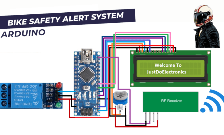
Smart Bike Safety Alert System Using Arduino
step by step guide for helmet safety alert system using arduino
Introduction
The Smart Bike Helmet is designed to enhance the safety of cyclists by incorporating various sensors and communication modules to detect accidents and notify emergency contacts. Smart Bike Helmets with an RF transmitter and receiver allow for wireless communication between the helmet and a base station or another device, enabling features such as remote monitoring or data exchange.
RF Transmitter and Receiver Integration
-
- Connect the RF transmitter module to the Arduino board. Ensure the appropriate power supply and connections are made.
- Connect the RF receiver module to the base station or another device that will communicate with the helmet.
- Use the Arduino’s digital pins to interface with the transmitter and receiver modules.
Data Transmission
-
-
- Determine what data needs to be transmitted from the helmet to the base station/device.
- Convert the sensor data or other relevant information into a suitable format for transmission.
- Use the RF transmitter module to send the data wirelessly to the receiver module.
-
Data Reception
-
-
- Configure the receiver module to listen for incoming data from the helmet.
- Implement code on the base station/device to receive and interpret the data received from the helmet.
- Process the received data as per your application requirements.
-
Component Need
- Arduino Nano
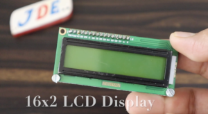
- 16×2 LCD Display
- Relay Module
- IR Sensor
- Push Button
- Buzzer
- LED
- BO motor
- Wires
- Zero PCB
- Power supply
Arduino Nano
- The Arduino Nano is used an ATmega328P microcontroller chip.
- The ATmega328P operates at a clock speed of 16 MHz.
- Flash memory 32KB.
- SRAM of 2KB.
- 1KB of EEPROM.
- The Nano is significantly smaller compared to other Arduino boards.
- The Arduino Nano provides a total of 14 digital I/O pins.
- 6 PIN used for PWM (Pulse Width Modulation) output.
- 8 PIN analog input pins.
- 10-bit resolution.
16×2 LCD Display
- A 16×2 LCD (Liquid Crystal Display) is a type of alphanumeric display commonly used in electronic devices and microcontroller-based systems.
- It consists of 16 columns and 2 rows, hence the name “16×2.” Each location in the display can hold a single character, typically composed of a combination of letters, numbers, and symbols.
RF Receiver
A 433MHz RF transmitter receiver wireless module is a pair of electronic components used for wireless communication at a frequency of 433 megahertz (MHz). The transmitter module sends data wirelessly, while the receiver module captures and receives those signals.
- Antenna: The receiver module has an antenna that captures the wireless signals transmitted by the RF transmitter. The antenna converts the RF signal into electrical signals.
- RF Receiver: The RF receiver section amplifies the received signals and filters out unwanted noise and interference. It then extracts the modulated data from the RF carrier signal.
- Decoder: The received and demodulated data is passed through a decoder, which decodes the modulation scheme applied during the encoding process. The decoder converts the received signals back into their original digital format.
- Data Output: The decoded data is then made available for further processing or use. It can be interfaced with a microcontroller or other devices to perform specific actions based on the received data.
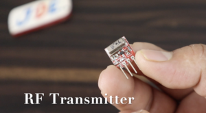
RF Transmitter
- Data Input: The transmitter module receives data or signals from a microcontroller or any other source that needs to be transmitted wirelessly. This data is typically in the form of digital signals.
- Encoder: The data input is usually encoded using a modulation scheme to convert it into a format suitable for wireless transmission. Common modulation schemes used in RF communication include amplitude shift keying (ASK), frequency shift keying (FSK), or on-off keying (OOK).
- RF Transmitter: The encoded signals are then fed into the RF transmitter, which generates an RF carrier signal at the designated frequency of 433MHz. The carrier signal is modulated with the encoded data to create the wireless signal.
- Antenna: The transmitter module includes an antenna that radiates the modulated RF signal into space for wireless transmission. The antenna helps propagate the signal and maximize its range.
Specifications of 433MHz RF Transmitter Receiver
- Range in open space(Standard Conditions) : 100 Meters
- RX Receiver Frequency: 433 MHz
- RX Typical Sensitivity: 105 Dbm
- RX Supply Current: 3.5 mA
- RX IF Frequency: 1MHz
- RX Operating Voltage: 5V
- TX Frequency Range: 433.92 MHz
- TX Supply Voltage: 3V ~ 6V
- TX Out Put Power: 4 ~ 12 Dbm
10k POT
A potentiometer consists of three terminals: two fixed outer terminals and a wiper terminal. The fixed outer terminals are connected to the ends of the resistive element, which is usually a strip of resistive material. The wiper terminal is a movable contact that can slide along the resistive strip, creating a variable resistance.
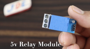
5v Relay Module
A 5V relay module is used to turn on the bike irrigation system if the person wears the Helmet then the relay will HIGH and if the person does not wear the Helmet then the relay will LOW which means the bike irrigation system will not start.
IR Sensor
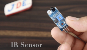
The IR (Infrared) sensor detects the Helmet if the person wearing the helmet then the sensor sends a LOGIC HIGH signal, And if the person not wearing the helmet then the IR Sensor send signal LOGIC LOW.
LED
The led is used for indication purposes.
PUSH Button
A push button is used for emergency purposes.
Buzzer
A buzzer produces a sound.
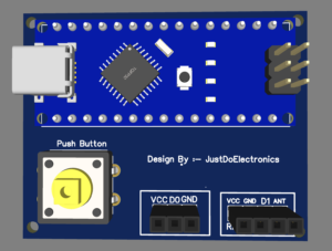
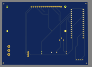
Zero PCB
A PCB is typically made of a flat, rigid board made of non-conductive material, such as fibreglass-reinforced epoxy or phenolic resin. The board is usually thin and has a copper layer on one of the Backsides.
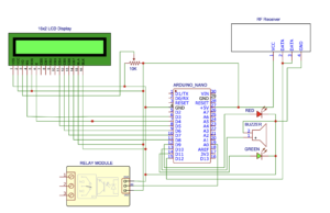
Circuit Diagram
Transmitter Circuit Diagram
Receiver Circuit Diagram
Source Code
Prototyping and Testing
-
- Assemble the components on the helmet and ensure proper mounting and wiring.
- Upload the Arduino code that implements the RF communication and desired functionality.
- Test the system by transmitting and receiving data, verifying the accuracy of communication and desired actions triggered by the received data.
Video Tutorial
Conclusion
Smart Bike Helmets with RF transmitters and receivers enhance cyclist safety through accident detection, emergency notification, remote monitoring, and data exchange. These features provide cyclists with an added layer of protection and enable seamless communication between the helmet, emergency services, and other devices or applications.
Arduino Based Projects










hello sir. can you provide arduino coding for this project
Can you provide the Code of smart helmet alert system