Introduction
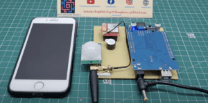
In this article, we will guide you through the process of creating a security alarm system using an Arduino Uno microcontroller board, a PIR (Passive Infrared) sensor, a SIM800L GSM module, and a buzzer. This system will detect motion using the PIR sensor and alert you via Call using the GSM module in case of any intrusions.
Components Needed
- Arduino Uno
- PIR Sensor
- GSM sim800l Module
- Buzzer
- Wire
- Zero PCB
- 9V power supply
Arduino Uno
- The Arduino Uno has used an ATmega328P microcontroller chip.
- The ATmega328P operates at a clock speed of 16 MHz.
- Flash memory 32KB.
- SRAM of 2KB.
- 1KB of EEPROM.
- The Uno is significantly smaller compared to other Arduino boards.
- The Arduino Uno provides a total of 14 digital I/O pins.
- 6 PIN used for PWM (Pulse Width Modulation) output.
- 6 PIN analog input pins.
- 10-bit resolution.
PIR Sensor
The PIR (Passive Infrared) sensor is a type of motion sensor commonly used in security systems and automation applications.
- The PIR sensor consists of a pyroelectric sensor, which is capable of detecting infrared radiation, and a lens that focuses the incoming radiation onto the sensor. The pyroelectric sensor is made of a crystalline material that generates an electrical charge when exposed to infrared radiation.
GSM sim800l Module
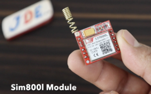
GSM SIM800L is a popular module that enables communication over GSM (Global System for Mobile Communications) networks. It provides functionalities for making calls, sending and receiving SMS messages, and connecting to the internet.
- The GSM SIM800L module is designed to work with GSM networks, allowing devices to establish communication through cellular networks. It operates on various frequencies and supports 2G, and 3G connectivity, making it compatible with most GSM networks worldwide.
- The module requires a power supply of around 3.7 to 4.2 volts.
Circuit Diagram
PIR Sensor
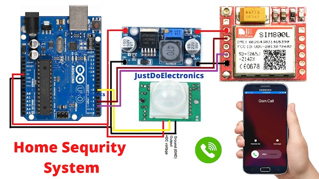
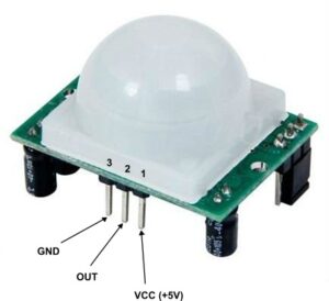
- The VCC pin of the PIR sensor to the 5V pin on the Arduino Uno.
- The GND (ground) pin of the PIR sensor to the GND pin on the Arduino Uno.
- The OUT pin of the PIR sensor to any digital input pin (6) on the Arduino Uno.
GSM Module
- The positive (VCC) and negative (GND) pins of the SIM800L GSM module to the 3.7 and GND pins on the LM2596 Step down converter, respectively.
- The TX (transmit) pin of the SIM800L GSM module to the RX (receive) pin (2) on the Arduino Uno.
- The RX (receive) pin of the SIM800L GSM module to the TX (transmit) pin (3) on the Arduino Uno.
Source Code
|
1 2 3 4 5 6 7 8 9 10 11 12 13 14 15 16 17 18 19 20 21 22 23 24 25 26 27 28 29 30 31 32 33 34 35 36 37 |
//Prateek //https://justdoelectronics.com //https://www.youtube.com/c/JustDoElectronics/videos #include <SoftwareSerial.h> const String PHONE = "+918830584864xx"; #define rxPin 2 #define txPin 3 SoftwareSerial sim800(rxPin, txPin); int pir_sensor = 6; void setup() { pinMode(pir_sensor, INPUT); Serial.begin(115200); sim800.begin(9600); Serial.println("SIM800L software serial initialize"); sim800.println("AT"); delay(1000); } void loop() { while (sim800.available()) { Serial.println(sim800.readString()); } while (Serial.available()) { sim800.println(Serial.readString()); } int val = digitalRead(pir_sensor); if (val == HIGH) { Serial.println("Motion detected!"); Serial.println("calling...."); delay(1000); sim800.println("ATD" + PHONE + ";"); delay(20000); } } |
Let’s go through the code and explain its functionality.
- Includes the required libraries and defines the necessary variables.
- Replace
+918830584864xxwith the desired phone number.
|
1 2 3 4 5 6 7 |
#include <SoftwareSerial.h> const String PHONE = "+918830584864xx"; #define rxPin 2 #define txPin 3 SoftwareSerial sim800(rxPin, txPin); int pir_sensor = 6; |
- The
setup()the function is called once at the start of the program. - It sets the
pir_sensorpin as an input.
|
1 2 3 4 5 6 7 8 |
void setup() { pinMode(pir_sensor, INPUT); Serial.begin(115200); sim800.begin(9600); Serial.println("SIM800L software serial initialize"); sim800.println("AT"); delay(1000); } |
- The
loop()the function runs continuously after thesetup()function. - It first checks if there is any data available from the GSM module. If so, it reads and prints it on the serial monitor.
|
1 2 3 4 5 6 7 8 9 10 11 12 13 14 15 16 |
void loop() { while (sim800.available()) { Serial.println(sim800.readString()); } while (Serial.available()) { sim800.println(Serial.readString()); } int val = digitalRead(pir_sensor); if (val == HIGH) { Serial.println("Motion detected!"); Serial.println("calling...."); delay(1000); sim800.println("ATD" + PHONE + ";"); delay(20000); } } |
Make sure to replace +918830584864xx it with the correct phone number.
Project Demo
- Set up the PIR sensor pin as an input and the buzzer pin as an output.
- If the motion is detected, trigger the alarm by sounding the buzzer and Call an alert using the GSM module.
Video
Conclusion
This DIY project can be used for the security system of your home and office. if you used the Pir sensor then be care full is detect some time fault signal. I suggest you if you try to make a motion-based security system you used an ultrasonic sensor.
Arduino Based Projects



Please make a GSM motor starter control this type https://bit.ly/3Oq2XJN