OTP Based Door Lock Using Arduino And SIM800L
OTP Based Door Lock Using Arduino And SIM800L GSM Module
Introduction
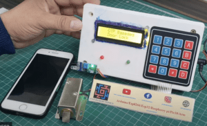
In this article, we will guide you through the process of creating an OTP (One-Time Password) based door lock system using Arduino and various components like I2C 16×2 LCD, relay, 4×4 keypad, and GSM SIM800L module.
The OTP-Based Door Lock System is designed to enhance the security of doors by implementing a one-time password authentication mechanism.
The system will enhance the security of your doors by requiring a unique password each time someone wants to gain access. Let’s get started!
Bill Of Materials
S.N | Component's | Quantity | Link To Buy |
1 | Arduino Uno | 1 | |
2 | 16x2 LCD Display With I2C | 1 | |
3 | 4x4 Keypad | 1 | |
4 | Sim800l GSM Module | 1 | |
5 | 5v Realy Module | 1 | |
6 | Zero PCB | 1 | |
7 | Buzzer | 1 | |
8 | 9V Battery | 1 |
Arduino Uno
Arduino Uno is a popular microcontroller board that is part of the Arduino family. It is widely used in various electronic projects and prototyping due to its simplicity and versatility. Here’s an explanation of the Arduino Uno
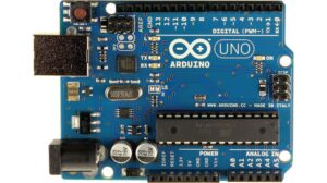
- The Arduino Uno is built around the Atmega328P microcontroller. This microcontroller has 32KB of flash memory, 2KB of SRAM, and 1KB of EEPROM. It operates at a clock speed of 16 MHz.
- The Arduino Uno features 14 digital input/output pins, marked as D0 to D13. These pins can be configured as either inputs or outputs.
- The board also includes 6 analog input pins (A0 to A5), which can measure voltage levels ranging from 0 to 5 volts. .
16×2 LCD Module With I2C
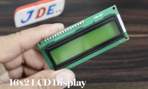
A 16×2 LCD display refers to a liquid crystal display with two rows and 16 characters per row. It is a commonly used alphanumeric display in many electronic projects and devices. The I2C (Inter-Integrated Circuit) interface is a communication protocol that allows for easy and efficient communication between microcontrollers.
- When an LCD display is connected using the I2C interface, it typically requires fewer pins compared to a direct parallel connection, making it more convenient for projects with limited available pins on the microcontroller.
- I2C Interface: The I2C interface uses a master-slave communication protocol. The microcontroller acts as the master and the LCD display module as the slave. The I2C interface allows for multiple devices to be connected on the same bus, each with a unique address.
- I2C Address: The LCD display module with an I2C interface has a specific address that is set by the manufacturer. This address can usually be found in the documentation or can be identified using an I2C scanner program.
Relay module
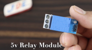
A relay module is an integrated circuit board that incorporates a relay and additional components for easy integration into electronic projects. It provides a convenient way to control higher voltage or current loads using a lower voltage signal, such as the output from a microcontroller or Arduino.
The relay itself is the primary component of the module. It consists of an electromagnet and a set of contacts. The contacts can be normally open (NO), normally closed (NC), or both, depending on the relay type. When the coil of the relay is energized, the contacts change their state.
4×4 keypad
A 4×4 keypad, also known as a matrix keypad, is a commonly used input device that provides a convenient interface for entering numerical or alphanumeric data. It consists of a grid of buttons arranged in a 4 by 4 configuration, where each button represents a specific input.
- A 4×4 keypad consists of 16 buttons arranged in a grid of four rows and four columns. Each button is a separate switch that can be pressed or released to generate a specific input.
GSM SIM800L module
GSM SIM800L is a popular module that enables communication over GSM (Global System for Mobile Communications) networks. It provides functionalities for making calls, sending and receiving SMS messages, and connecting to the internet.
- If Your GSM does Not Work Then Read Article Sim800l GSM Module Working
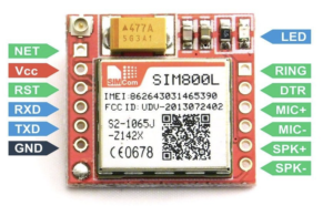
- The module requires a power supply of around 3.7 to 4.2 volts. It can be powered using an external power source. It is important to ensure a stable power supply to ensure reliable operation.
- The module communicates with other devices, such as microcontrollers or computers, using serial communication. It typically utilizes the UART (Universal Asynchronous Receiver-Transmitter) protocol.
Circuit Diagram
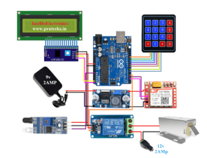
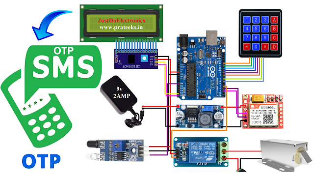
- Connect the I2C 16×2 LCD module to the Arduino using the SDA(A4) and SCL(A5) pins.
- Connect the relay module to the Arduino’s digital pin 4, which will control the door lock mechanism.
- Connect the 4×4 keypad to the Arduino using digital pins (13,12,11,10,9,8,7,6) for both row and column connections.
- Connect the GSM SIM800L module to the Arduino’s serial pins (3 and 2) and power it using a separate power supply.
- Connect the IR Sensor module to the Arduino’s Analog pins A0.
Code
Before you Upload the Code is required to install the library First.
|
1 2 3 4 5 6 7 8 9 10 11 12 13 14 15 16 17 18 19 20 21 22 23 24 25 26 27 28 29 30 31 32 33 34 35 36 37 38 39 40 41 42 43 44 45 46 47 48 49 50 51 52 53 54 55 56 57 58 59 60 61 62 63 64 65 66 67 68 69 70 71 72 73 74 75 76 77 78 79 80 81 82 83 84 85 86 87 88 89 90 91 92 93 94 95 96 97 98 99 100 101 102 103 104 105 106 107 108 109 110 111 112 113 114 115 116 117 118 119 120 121 122 123 124 125 126 127 128 129 130 131 132 133 134 135 136 137 |
//Prateek //wwww.justdoelectronics.in //https://www.youtube.com/c/JustDoElectronics/videos #include <SoftwareSerial.h> #include <Wire.h> #include <LiquidCrystal_I2C.h> #include <Keypad.h> #define relay 4 #define red 16 #define green 15 const byte ROWS = 4; const byte COLS = 4; char hexaKeys[ROWS][COLS] = { { '1', '2', '3', 'A' }, { '4', '5', '6', 'B' }, { '7', '8', '9', 'C' }, { '*', '0', '#', 'D' } }; byte rowPins[ROWS] = { 13, 12, 11, 10 }; byte colPins[COLS] = { 9, 8, 7, 6 }; Keypad customKeypad = Keypad(makeKeymap(hexaKeys), rowPins, colPins, ROWS, COLS); LiquidCrystal_I2C lcd(0x27, 16, 2); SoftwareSerial sim800l(3, 2); int irsensor = A0; int otp; String otpstring = ""; int i = 0; void setup() { pinMode(irsensor, INPUT_PULLUP); sim800l.begin(4800); Serial.begin(115200); lcd.init(); lcd.backlight(); Serial.print("Welcome to SIM800L Project"); sim800l.println("AT"); updateSerial(); pinMode(relay, OUTPUT); pinMode(red, INPUT); pinMode(green, INPUT); digitalWrite(relay, LOW); delay(500); sim800l.println("AT+CSQ"); updateSerial(); delay(1000); } void updateSerial() { delay(500); while (Serial.available()) { sim800l.write(Serial.read()); } while (sim800l.available()) { Serial.write(sim800l.read()); } } void loop() { lcd.setCursor(0, 0); lcd.print(" OTP Based"); lcd.setCursor(0, 1); lcd.print(" Door Lock"); if (digitalRead(irsensor) == LOW) { otp = random(2000, 9999); otpstring = String(otp); Serial.println(otpstring); while (digitalRead(irsensor) == LOW) {} lcd.clear(); lcd.setCursor(0, 0); lcd.print(" OTP Sent to"); lcd.setCursor(0, 1); lcd.print(" Your Mobile"); Serial.print("OTP is "); delay(100); Serial.println(otpstring); delay(100); SendSMS(); lcd.clear(); lcd.setCursor(0, 0); lcd.print("Enter OTP :"); getotp(); } } void getotp() { String y = ""; int a = y.length(); while (a < 4) { char customKey = customKeypad.getKey(); if (customKey) { lcd.setCursor(0, 1); y = y + customKey; lcd.print(y); a = y.length(); } } Serial.print("Entered OTP is "); Serial.println(y); if (otpstring == y) { lcd.setCursor(0, 0); lcd.print("Access Granted"); lcd.setCursor(0, 1); lcd.print("Door Opening"); digitalWrite(relay, HIGH); digitalWrite(red, HIGH); digitalWrite(green, LOW); delay(5000); digitalWrite(relay, LOW); digitalWrite(red, LOW); digitalWrite(green, HIGH); } else { lcd.setCursor(0, 0); lcd.print("Access Failed"); lcd.setCursor(0, 1); lcd.print("Try Again !!!"); delay(3000); } } void SendSMS() { Serial.println("Sending SMS..."); sim800l.print("AT+CMGF=1\r"); delay(100); sim800l.print("AT+CSMP=17,167,0,0\r"); delay(500); sim800l.print("AT+CMGS=\"+91xxxxxxxxxxx\"\r"); delay(500); sim800l.print("Your OTP is " + otpstring + " Just Type OTP And Unlock The Door"); delay(500); sim800l.print((char)26); delay(500); sim800l.println(); Serial.println("Text Sent."); delay(500); } |
Video
Arduino Based Projects
- Smart Bike And Car Starter
- Fingerprint Sensor-Based Biometric Security System
- Rfid And Fingerprint Bike And Car Ignition System
- Fingerprint And Alcohol Sensor-Based Bike Ignition System
- Fingerprint And Rfid Based Bike And Car Ignition Systems
- Fingerprint-Based Biometric Voting Machine Project
Conclusion
By following this guide, you have successfully built an OTP-based door lock system using Arduino, an I2C 16×2 LCD, a relay module, a 4×4 keypad, and a GSM SIM800L module. This system provides additional security to your doors, ensuring that only authorized individuals with the correct OTP can gain access.
