
Introduction
In This, Article You Learn How To Interface with The ADXL-335 Sensor With Arduino And I will Show you how you Clabite The ADXL-335 sensor.
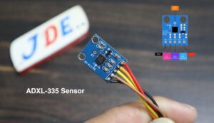
ADXL-335 An accelerometer is an electromechanical device that will measure acceleration forces in the form of The Analog Value And provide output In the Form Of X, Y, And Z directions. with the help of all directions, you create so many Projects.
Bill Of Materials
S.N | Component | Quantity | Buy To Link |
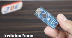
1 | Arduino Nano | 1 | |
2 | ADXL-345 | 1 | |
3 | GSM SIM800l | 1 | |
4 | GPS Neo-6m | 1 | |
5 | LM2596 Step Conveter | 1 | |
6 | Zero PCB | 1 |
Sim800l GSM Module
SIM800l GSM Module, designed by Simcom. This module operates at a voltage of 3.4v to 4.4v, it is powered directly with a lithium-ion battery and LM2596 step-down converter.
The comes with an IPX antenna interface that allows switching between a PCB antenna and a suction cup antenna.
Note – The Module is compatible with any 2G-3G SIM card.
Led status indicator
The sim800l module has an LED indicator that shows the network conduction.
- Blinking every 1 second – The module is powered on but not connected to the network.
- Blinking every 2 seconds – The GPRS data connection is active and ready for data Transfer.
- Blinking every 3 seconds – The Module is connected to a network and ready to send/receive SMS messages And Calls.
Neo-6M GPS Module
The Neo-6M GPS module is developed by U-blox.
The GPS Module in Full form is (the Global Positioning System) it uses 31 satellites orbiting Earth to transmit location and date/time.
Led indicator
on the neo-6M GPS Module Board, there’s is a small LED that shows the condition of communication status with satellite:
- No, blinking means the GPS module is searching for satellites.
- Blinking Every 1 Second Means the position is fixed and is connected to the satellite.
LM2596 StepDown Converter
ADXL-335 Sensor
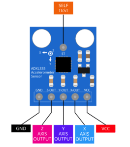
This module can be used to sense motion (in the case of non-moving) in 3 axes. This is the latest in a long, proven line of Analog Sensors- the holy grail of accelerometers.
PIN
- Operating Voltage :- 3.7 To 5v
- Value :- Analog Value
- Direction:- X-axis, Y-axis, And Z-axis
Features
- ADXL335: 3-axis sensing.
- Small, low-profile package.
- Low power: 350 μA.
- Single-supply operation: 1.8 V to 3.6 V.
- Excellent temperature stability.
- BW adjustment with a single capacitor per axis.
- RoHS/WEEE is lead-free compliant.
More GPS Related Projects.
- GPS & Gsm location Tracking System Using Arduino
- Dam Monitoring System Using Arduino
- Arduino Based Blind Stick With GPS And GSM
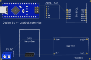
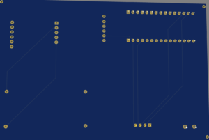
PCB Design
Front Side
Back Side
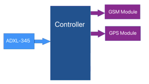
Block Diagram
Here I Show The Block Diagram In this Project, On the Input Side I connected to the ADXL-335 Sensor and on the Output Side, I connected To The GSM Sim800l And GPS Neo-6m Module.
If any Movement is detected The ADXL-335 Sensor Crosses the Threshold Value And GSM Send The Text Message.
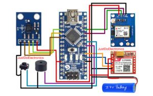
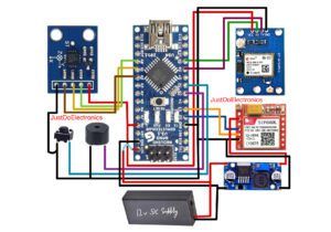
Circuit Diagram
The ADXL-335 Sensor Is Connected To The Pin Number:
- VCC 5v
- GND GND
- X-Axis A0
- Y-Axis A1
- Z-Axis A2
GSM SI800l Module Will be connected To The PIN Number:
- VCC 3.7v
- GND GND
- Tx D2
- Rx D3
GPS Neo-6M Module Will be connected To The Pin Number:
- VCC 5v
- GND GND
- Tx D8
- Rx D9
The Buzzer Will be connected To The Pin Number:
- GND GND
- DO D5
The Push Button Will be connected To The Pin Number:
- GND GND
- DO D6
In this circuit Diagram, I Used the LM2596 Stepdown Converter
Source Code/Program
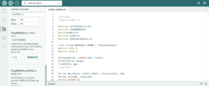
Before You Uploading the Code You are Required To Add the Library first.

Change the Mobile Number
|
1 |
const String EMERGENCY_PHONE = "+91xxxxxxxxxx"; |
|
1 2 3 4 5 6 7 8 9 10 11 12 13 14 15 16 17 18 19 20 21 22 23 24 25 26 27 28 29 30 31 32 33 34 35 36 37 38 39 40 41 42 43 44 45 46 47 48 49 50 51 52 53 54 55 56 57 58 59 60 61 62 63 64 65 66 67 68 69 70 71 72 73 74 75 76 77 78 79 80 81 82 83 84 85 86 87 88 89 90 91 92 93 94 95 96 97 98 99 100 101 102 103 104 105 106 107 108 109 110 111 112 113 114 115 116 117 118 119 120 121 122 123 124 125 126 127 128 129 130 131 132 133 134 135 136 137 138 139 140 141 142 143 144 145 146 147 148 149 150 151 152 153 154 155 156 157 158 159 160 161 162 163 164 165 166 167 168 169 170 171 172 173 174 175 176 177 178 179 180 181 182 183 184 185 186 187 188 189 190 191 192 193 194 195 196 197 198 199 200 201 202 203 204 205 206 207 208 209 210 211 212 213 214 215 216 217 218 219 220 221 222 223 224 225 226 227 228 229 230 231 232 233 234 235 236 237 238 239 240 241 242 243 244 245 246 247 248 249 250 251 252 253 254 255 256 257 258 259 260 261 262 263 264 265 266 267 268 269 270 271 272 273 274 275 276 277 278 279 280 |
//Prateek //www.justdoelectronics.com #include <AltSoftSerial.h> #include <TinyGPS++.h> #include<Wire.h> #include <math.h> #include <SoftwareSerial.h> const String EMERGENCY_PHONE = "+91xxxxxxxxxx"; #define rxPin 2 #define txPin 3 SoftwareSerial sim800(rxPin, txPin); AltSoftSerial neogps; TinyGPSPlus gps; //RX Pin To D9 //TX Pin To D8 String sms_status, sender_number, received_date, msg; String latitude, longitude; #define BUZZER 5 #define BUTTON 6 #define xPin A0 #define yPin A1 #define zPin A2 byte updateflag; int xaxis = 0, yaxis = 0, zaxis = 0; int deltx = 0, delty = 0, deltz = 0; int vibration = 2; int devibrate = 75; int magnitude = 0; int sensitivity = 20; double angle; boolean impact_detected = false; unsigned long time1; unsigned long impact_time; unsigned long alert_delay = 30000; void setup() { Serial.begin(9600); sim800.begin(9600); neogps.begin(9600); pinMode(BUZZER, OUTPUT); pinMode(BUTTON, INPUT_PULLUP); sms_status = ""; sender_number = ""; received_date = ""; msg = ""; sim800.println("AT"); delay(1000); sim800.println("ATE1"); delay(1000); sim800.println("AT+CPIN?"); delay(1000); sim800.println("AT+CMGF=1"); delay(1000); sim800.println("AT+CNMI=1,1,0,0,0"); delay(1000); time1 = micros(); xaxis = analogRead(xPin); yaxis = analogRead(yPin); zaxis = analogRead(zPin); } void loop() { if (micros() - time1 > 4999) Impact(); if (updateflag > 0) { updateflag = 0; Serial.println("Impact detected!!"); Serial.print("Magnitude:"); Serial.println(magnitude); getGps(); digitalWrite(BUZZER, HIGH); impact_detected = true; impact_time = millis(); } if (impact_detected == true) { if (millis() - impact_time >= alert_delay) { digitalWrite(BUZZER, LOW); makeCall(); delay(1000); sendAlert(); impact_detected = false; impact_time = 0; } } if (digitalRead(BUTTON) == LOW) { delay(200); digitalWrite(BUZZER, LOW); impact_detected = false; impact_time = 0; } while (sim800.available()) { parseData(sim800.readString()); } while (Serial.available()) { sim800.println(Serial.readString()); } } void Impact() { time1 = micros(); int oldx = xaxis; int oldy = yaxis; int oldz = zaxis; xaxis = analogRead(xPin); yaxis = analogRead(yPin); zaxis = analogRead(zPin); vibration--; Serial.print("Vibration = "); Serial.println(vibration); if (vibration < 0) vibration = 0; if (vibration > 0) return; deltx = xaxis - oldx; delty = yaxis - oldy; deltz = zaxis - oldz; magnitude = sqrt(sq(deltx) + sq(delty) + sq(deltz)); if (magnitude >= sensitivity) //impact detected { updateflag = 1; vibration = devibrate; } else { magnitude = 0; } } void parseData(String buff) { Serial.println(buff); unsigned int len, index; index = buff.indexOf("\r"); buff.remove(0, index + 2); buff.trim(); if (buff != "OK") { index = buff.indexOf(":"); String cmd = buff.substring(0, index); cmd.trim(); buff.remove(0, index + 2); if (cmd == "+CMTI") { index = buff.indexOf(","); String temp = buff.substring(index + 1, buff.length()); temp = "AT+CMGR=" + temp + "\r"; sim800.println(temp); } else if (cmd == "+CMGR") { if (buff.indexOf(EMERGENCY_PHONE) > 1) { buff.toLowerCase(); if (buff.indexOf("get gps") > 1) { getGps(); String sms_data; sms_data = "GPS Location Data\r"; sms_data += "http://maps.google.com/maps?q=loc:"; sms_data += latitude + "," + longitude; sendSms(sms_data); } } } } else { } } void getGps() { // Can take up to 60 seconds boolean newData = false; for (unsigned long start = millis(); millis() - start < 2000;) { while (neogps.available()) { if (gps.encode(neogps.read())) { newData = true; break; } } } if (newData) { latitude = String(gps.location.lat(), 6); longitude = String(gps.location.lng(), 6); newData = false; } else { Serial.println("No GPS data is available"); latitude = ""; longitude = ""; } Serial.print("Latitude= "); Serial.println(latitude); Serial.print("Lngitude= "); Serial.println(longitude); } void sendAlert() { String sms_data; sms_data = "Accident Alert!!\r"; sms_data += "http://maps.google.com/maps?q=loc:"; sms_data += latitude + "," + longitude; sendSms(sms_data); } void makeCall() { Serial.println("calling...."); sim800.println("ATD" + EMERGENCY_PHONE + ";"); delay(20000); //20 sec delay sim800.println("ATH"); delay(1000); //1 sec delay } void sendSms(String text) { //return; sim800.print("AT+CMGF=1\r"); delay(1000); sim800.print("AT+CMGS=\"" + EMERGENCY_PHONE + "\"\r"); delay(1000); sim800.print(text); delay(100); sim800.write(0x1A); delay(1000); Serial.println("SMS Sent Successfully."); } boolean SendAT(String at_command, String expected_answer, unsigned int timeout) { uint8_t x = 0; boolean answer = 0; String response; unsigned long previous; while ( sim800.available() > 0) sim800.read(); sim800.println(at_command); x = 0; previous = millis(); do { if (sim800.available() != 0) { response += sim800.read(); x++; if (response.indexOf(expected_answer) > 0) { answer = 1; break; } } } while ((answer == 0) && ((millis() - previous) < timeout)); Serial.println(response); return answer; } |
Demo Of Project
Output Of The Project
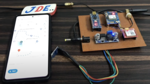
In 1st Image, The ADXL-335 Sensor Detecd Is Rafe Movement Then GSM Send The Text Message To a particular Mobile Number
When You Click The Text Message The Link Will Activated And Open
In Google Maps You Track The location In Real Time With The Help Of GPS
If You are Interested In More Projects Then Plz Check Out




Iwant the code with display and with display diagram
I want such types of Projects and Detailed Video about Robotics.
What did you use to draw the digram of circuit. Can you please let me know?
I want this code without error
This Vehicle Accident Alert System sounds like a game changer! It’s great to see technology being used to enhance road safety. I hope to see more development in this area to help reduce response times in emergencies. Can’t wait to hear about its real-world impact!
This Vehicle Accident Alert System sounds like a game changer! It’s impressive how technology can enhance safety on the roads. I can’t wait to see how it evolves and helps reduce response times in emergencies. Great post!
This Vehicle Accident Alert System sounds like a game changer! The potential to improve response times and save lives is incredible. I’m curious about how it integrates with existing emergency services and if it can be applied to older vehicle models. Looking forward to seeing how this technology evolves!
This is such an interesting concept! The Vehicle Accident Alert System could really change how we respond to emergencies on the road. I love the idea of using technology to potentially save lives and improve safety. Looking forward to seeing how this develops!
This Vehicle Accident Alert System is a game changer! It’s great to see technology stepping up to enhance road safety. I can only imagine how many lives could be saved with quicker responses to accidents. Looking forward to seeing how it evolves!
This is a fantastic initiative! The Vehicle Accident Alert System could greatly enhance road safety and response times. I’m curious about the technology behind it and how it determines the severity of an accident. Looking forward to seeing how this develops!
This Vehicle Accident Alert System sounds like a fantastic innovation! It’s great to see technology being utilized to improve road safety and ensure timely assistance in case of accidents. I can’t wait to hear more about its features and how it will be implemented!
This Vehicle Accident Alert System sounds like a game changer! It’s incredible to see technology being used to enhance safety on the roads. I can only imagine how helpful it would be for emergency responders as well. Looking forward to seeing more advancements in this area!