Dam Monitoring System Using Arduino
Introduction
Photo Credit By- punekarnews
During the rainy season, floods are very natural to occur. But if they occur heavily then problems will arise. Then I thought about this project, you are going to build an automatic Dam Monitoring System Using GSM Module And Arduino Nano.
In this project I will just show the dam protection and monitoring system. the Ultrasonic Sensor find the proper water level and display the level in a 16×2 LCD Display and the float Sensor Providing Alert Information When the Dam Water Full And Is crosses the threshold Value of the gsm send the text message and buzzer is beeping I mean the providing alert to people.
Bill Of Material
In This Project, I used this Component
S.N | Component Name | Quanitity | Link To Buy |
1 | Arduino Nano | 1 | |
2 | Ultersonic Sensor | 1 | |
3 | Float Sensor | 1 | |
4 | LM2596 Step Down Converter | 1 | |
5 | GSM Sim800l | 1 | |
6 | 16x2 Lcd Display | 1 | |
7 | Buzzer | 1 | |
8 | Led | 1 | |
9 | 10k PoT | 1 | |
10 | Led | 1 | |
11 | Zero PCB | 1 |
Hardware Part
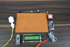
Here Is The Hardware Part Which I used in This Project.
In this Project, I used the Arduino Nano microcontroller. if you have another microcontroller then you also used it.
The Arduino Nano microcontroller has 13 Digital Pin And 8 Analogue pins.
16×2 Lcd Display I used because I want a small size of Display if you have another display than you also used.
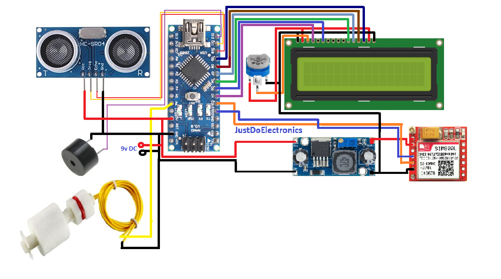
16×2 LCD Display connected to the PIN number D4,D5,D6,D7,D8 And D9 To Arduino Nano Microcontroller.
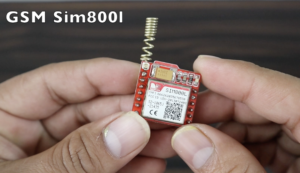
Here I Used The Sim800l GSM Module And Is required The 3.7v Then is work Properly That’s I Used The LM2596 Step-Down Converter The Convert The Input Voltage And is Providing The Proper 3.7 Volt To The GSM Module.
GSM Module Connected To The PIN D2, D3 To Arduino Nano.
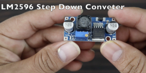
LM2596 Is Step Down Converter The Covert 12v DC Input To 3.7V Dc Output. That’s the output voltage I provide To the Gsm Module.
Led is Used In This Project The incited When Dam is Full The Led Will On And When Is not Full The Led Will Be Off.
Led I will connect the PIN A6 To Arduino Nano.
HC-SR 04 Ultrasonic Sensor Find Out the Proper Water Level And the Lcd Will Display The Real-Time Level.
Ultrasonic Sensor Connected to the PIN D10, D11 To Arduino Nano.
Float Sensor Provide The Alert Information When The Water Level Reach The Threshold Value.
Float Sensor Connected To The Pin Number A7 To Arduino Nano Board.
Dc Female Socket I Used Because of the External Supply I gave to the LM2596 Step Down Converter.
12v Dc Supply I Connected to the Dc Female Socket.
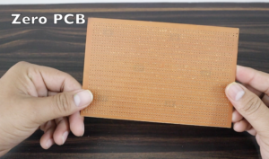
4×6 Zero PCB is Used In this Project Because in Project We Have More connections That’s Why I Soldering All Components in this Zero PCB.
Circuit Diagram
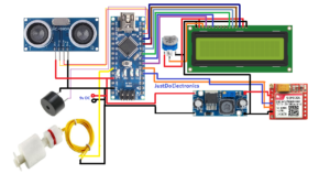
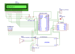
In This Circuit Diagram, I will show them where I connected all the sensors and module connected to the Arduino Nano microcontroller.
PCB Design

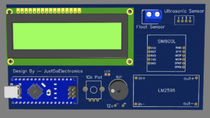
Download Gerber File:- https://drive.google.com/file/d/1kZx4opFXxD1A_OuyM8ix4fyO5BD_r77-/view?usp=share_link
Code
|
1 2 3 4 5 6 7 8 9 10 11 12 13 14 15 16 17 18 19 20 21 22 23 24 25 26 27 28 29 30 31 32 33 34 35 36 37 38 39 40 41 42 43 44 45 46 47 48 49 50 51 52 53 54 55 56 57 58 59 60 61 62 63 64 65 66 67 68 69 70 71 72 73 74 75 76 77 78 79 80 81 82 83 84 85 86 87 88 89 90 91 92 93 94 95 96 |
//Prateek //www.justdoelectronics.com #include <LiquidCrystal.h> #include <SoftwareSerial.h> LiquidCrystal lcd(4,5,6,7,8,9); #include <Wire.h> #define rxPin 2 #define txPin 3 SoftwareSerial sim800(rxPin, txPin); #define trigPin 11 #define echoPin 10 int FloatSensor = A7; int led = A6; int led2 = A5; int Relay = A4; int buttonState = 1; int tankFullAlertSent = 0; int tankEmptyAlertSent = 0; void setup() { pinMode(trigPin, OUTPUT); pinMode(echoPin, INPUT); Serial.begin(9600); sim800.begin(9600); Serial.println("SIM800L software serial initialize"); sim800.println("AT"); delay(1000); lcd.begin(16, 2); lcd.clear(); lcd.setCursor(0, 0); lcd.print(" Welcome To"); lcd.setCursor(0, 1); lcd.print(" Our Projects"); delay(2000); lcd.clear(); pinMode(FloatSensor, INPUT_PULLUP); pinMode(led, OUTPUT); pinMode(led2, OUTPUT); pinMode(Relay, OUTPUT); digitalWrite(Relay, LOW); } void loop() { buttonState = digitalRead(FloatSensor); long time_duration, distance_in_cm; digitalWrite(trigPin, LOW); delayMicroseconds(2); digitalWrite(trigPin, HIGH); delayMicroseconds(10); digitalWrite(trigPin, LOW); time_duration = pulseIn(echoPin, HIGH); distance_in_cm = time_duration / 29 / 2; Serial.print(distance_in_cm); Serial.println(" cm"); lcd.clear(); lcd.setCursor(3, 0); lcd.print("Water Dam"); lcd.setCursor(0, 1); lcd.print("Water level:"); lcd.setCursor(13, 1); lcd.print(distance_in_cm); if (buttonState == HIGH) { digitalWrite(led, HIGH); digitalWrite(led2, LOW); digitalWrite(Relay, HIGH); Serial.println("WATER LEVEL - LOW"); if (tankEmptyAlertSent == 0) { tankEmptyAlertSent = 1; tankFullAlertSent = 0; } } else { digitalWrite(led, LOW); digitalWrite(led2, HIGH); digitalWrite(Relay, LOW); Serial.println("WATER LEVEL - HIGH"); if (tankFullAlertSent == 0) { tankFullAlertSent = 1; tankEmptyAlertSent = 0; } } delay(1000); } |
Demo Of Project
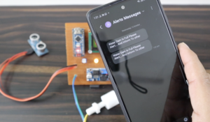
In the Image I will just put the float sensor on up side the buzzer is beeping and gsm is ready to send a text message to a particular Mobile Number.
Ok Now Here is the message that comes to mobile And Is displays the Water Dam is Full.







Please send full code of dam monitoring system using Arduino and GSM module