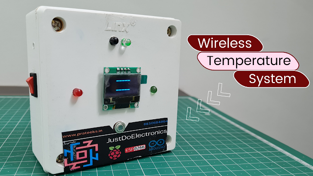
Temperature Monitoring System Using MLX90614 Sensor & Arduino
Introduction
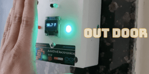
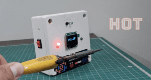
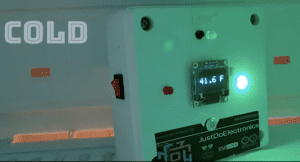
- This article presents a detailed guide on building a temperature monitoring system using an Arduino Nano, an IR sensor, an MLX90614 temperature sensor, and an OLED display.
- Temperature monitoring is essential in various applications, including environmental monitoring, industrial processes, and home automation. By combining the capabilities of Arduino, an IR sensor for presence detection, the accuracy of the MLX90614 sensor, and the visual display of the OLED screen, we can create an efficient and comprehensive temperature monitoring solution.
Components Needed
- Arduino Nano
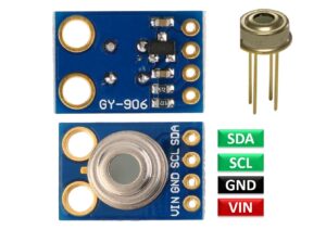
- MLX90614 Temperature Sensor
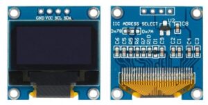
- OLED Display
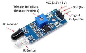
- IR Sensor
- Buzzer
- Red & Green Led
- Power Supply
Arduino Nano
- The Arduino Nano is powered by the ATmega328P microcontroller, which runs at a clock speed of 16 MHz. It has 32KB of flash memory for storing the program code, 2KB of SRAM for data storage, and 1KB of EEPROM for non-volatile data storage.
- Arduino Nano
- Digital and Analog I/O Pins: The Nano features a total of 22 digital input/output (I/O) pins, of which 14 can be used as PWM (Pulse Width Modulation) output pins. It also has 8 analog input pins for reading analog sensor values.
- Communication Interfaces: The Nano supports serial communication through its built-in USB-to-Serial converter, which allows for easy programming and communication with a computer. It also has dedicated hardware UART, SPI, and I2C interfaces for interfacing with other devices.
MLX90614 Temperature Sensor
- Infrared Detection: The sensor has an infrared-sensitive element called a thermopile that can detect infrared radiation emitted by an object. Different materials and objects emit different amounts of infrared radiation based on their temperature.
- Thermopile Measurement: The thermopile absorbs infrared radiation and converts it into an electrical signal. The sensor’s design ensures that the detected infrared energy is proportional to the temperature of the object being measured.
- Ambient Temperature Compensation: To obtain accurate temperature measurements, the MLX90614 also incorporates an ambient temperature sensor. This sensor measures the temperature of the surrounding environment to compensate for any variations that could affect the infrared readings.
- Calibration and Signal Processing: The sensor includes calibration data stored in its internal memory, which compensates for any inherent sensor variations and improves measurement accuracy. The microcontroller or device connected to the MLX90614 can access this calibration data to ensure accurate temperature calculations.
- I2C Communication: The MLX90614 communicates with the microcontroller or other devices through the I2C protocol. The microcontroller sends commands to the sensor to initiate temperature measurements, read the measured temperatures, and access calibration data.
Key Features
- Non-contact Measurement: The MLX90614 sensor can measure temperature without making direct contact with the object being measured. This feature is useful for applications where physical contact is not desired or feasible.
- Wide Temperature Range: The sensor can measure temperatures ranging from -70°C to +380°C (-94°F to +716°F), covering a broad range of temperature requirements.
- High Accuracy: The MLX90614 provides accurate temperature measurements with a resolution of 0.02°C.
- Two Channels: The sensor has two channels: one for measuring the object’s temperature (TO) and another for measuring the ambient temperature (TA).
- I2C Communication: The MLX90614 communicates with microcontrollers or other devices using the I2C (Inter-Integrated Circuit) protocol, making it compatible with a wide range of platforms.
OLED Display
OLED displays work by emitting light through organic compounds that are sandwiched between two electrodes. When a voltage is applied to the electrodes, it causes the organic compounds to emit light. Here’s a simplified explanation of the working principle:
- Pixel Illumination: Each pixel in the OLED display consists of tiny organic diodes that emit light independently. When a voltage is applied to a specific pixel, the organic compounds emit light at a specific wavelength.
- Colour Emission: The colour emitted by each pixel is determined by the organic compounds used in the display. Depending on the display module, it can be monochrome (typically white or blue) or a multi-colour display.
- Driving Circuitry: The display module includes driving circuitry that controls the voltage applied to each pixel. By adjusting the voltage levels, the display can control the brightness of individual pixels, allowing for the display of different shades and intensities.
- Display Control: The microcontroller or device connected to the OLED display sends commands and data through the communication protocol (I2C or SPI) to control which pixels should be illuminated and the content to be displayed. This allows for the rendering of text, numbers, graphics, and animations on the screen.
Key Features
- Display Technology: The 0.96-inch OLED display utilizes organic compounds that emit light when an electric current is applied. Unlike LCD (Liquid Crystal Display) screens, OLED displays do not require a backlight, resulting in high contrast and deep black levels.
- Screen Size and Resolution: The display has a 0.96-inch screen size, typically with a resolution of 128×64 pixels. This resolution provides sufficient detail for displaying text, numbers, and simple graphics.
- Active Display Area: The active display area refers to the portion of the screen where the content is visible. In a 0.96-inch OLED display, the active area usually measures around 21.74mm x 10.86mm.
- Communication Protocol: The display module communicates with the microcontroller or other devices using common protocols like I2C (Inter-Integrated Circuit) or SPI (Serial Peripheral Interface). This enables easy integration with various microcontrollers and reduces the number of required connections.
- High Contrast and Wide Viewing Angle: OLED displays offer excellent contrast ratios, resulting in vibrant colors and sharp text. Additionally, they provide a wide viewing angle, allowing the content to be easily visible from different perspectives.
- Low Power Consumption: OLED displays consume less power compared to traditional LCD displays since OLEDs only illuminate the individual pixels that need to be displayed. This characteristic makes them ideal for battery-powered devices or applications with power constraints.
IR Sensor
IR (Infrared) sensor, also known as an IR detector or IR receiver, is a device that detects and responds to infrared radiation. Infrared radiation is a type of electromagnetic radiation with wavelengths longer than visible light but shorter than radio waves. IR sensors are widely used in various applications for proximity sensing, object detection, presence detection, and remote control functionality. Here’s an explanation of the key features and working principles of an IR sensor
Key Features
- Sensing Range: IR sensors have a specific sensing range, which determines the distance over which they can detect infrared radiation. The sensing range can vary depending on the type and design of the IR sensor.
- Sensitivity: IR sensors are designed to be sensitive to specific wavelengths of infrared radiation. They can be optimized to detect certain types of infrared signals emitted by objects or sources.
- Output Signal: When an IR sensor detects infrared radiation, it generates an electrical signal as an output. This signal can be analog or digital, depending on the sensor’s design and purpose.
- Filtering Capabilities: Some IR sensors incorporate filters to limit the detection of specific types of infrared radiation. This allows them to ignore interference from ambient light sources or other infrared sources that are not of interest.
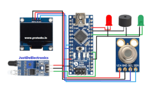
Circuit Diagram
Code
|
1 2 3 4 5 6 7 8 9 10 11 12 13 14 15 16 17 18 19 20 21 22 23 24 25 26 27 28 29 30 31 32 33 34 35 36 37 38 39 40 41 42 43 44 45 46 47 48 49 50 51 52 53 54 55 56 57 58 59 60 61 62 63 64 65 66 67 68 69 70 71 72 73 74 75 76 77 78 79 80 81 82 83 84 85 86 87 88 89 90 91 92 93 94 95 96 97 98 99 100 101 102 103 104 105 106 107 108 109 110 111 112 113 114 115 116 117 118 119 120 121 122 123 124 125 126 127 128 129 130 131 132 133 134 135 136 137 138 139 140 141 142 143 144 145 146 147 148 149 150 151 152 153 154 155 156 157 158 |
#include <Adafruit_SSD1306.h> #include <Adafruit_MLX90614.h> #include <Wire.h> #include <millisDelay.h> #define SCREEN_WIDTH 128 #define SCREEN_HEIGHT 64 const int GREEN_LED = 5; const int RED_LED = 6; const int buzzer = 8; const int statePin = 10; bool measurement = false; const unsigned long interval_sensor = 50; millisDelay sensorDelay; const unsigned long interval_display = 500; millisDelay displayDelay; const unsigned long delay_hold_red = 5000; const unsigned long delay_hold_green = 1000; millisDelay holdDelay; Adafruit_SSD1306 display(SCREEN_WIDTH, SCREEN_HEIGHT, &Wire, -1); Adafruit_MLX90614 mlx = Adafruit_MLX90614(); void setup() { Serial.begin(9600); if (!display.begin(SSD1306_SWITCHCAPVCC, 0x3C)) { Serial.println(F("OLED Display allocation failed")); for (;;) ; } pinMode(statePin, INPUT); pinMode(GREEN_LED, OUTPUT); pinMode(RED_LED, OUTPUT); pinMode(buzzer, OUTPUT); display.clearDisplay(); display.setTextSize(1); display.setTextColor(WHITE); display.setCursor(20, 20); display.println("Initializing"); display.display(); delay(250); display.clearDisplay(); mlx.begin(); displayDelay.start(interval_display); } void loop() { static float temperature = -1; int state = digitalRead(statePin); if (state == LOW && measurement == false) { sensorDelay.start(interval_sensor); displayDelay.finish(); measurement = true; } if (measurement == true) { //if sensor reading temperature = GetTemp(); } else { temperature = -1; } ShowTemp(temperature); holdReading(); } float GetTemp() { static int index = 0; static float temptot = 0; float hasil = 0; if (sensorDelay.justFinished()) { sensorDelay.repeat(); temptot += mlx.readObjectTempF(); index++; if (index == 19) { hasil = temptot / 20; temptot = 0; index = 0; sensorDelay.stop(); displayDelay.finish(); return hasil; } } return hasil; } void ShowTemp(float temperature) { if (displayDelay.justFinished()) { displayDelay.repeat(); if (temperature == -1) { display.clearDisplay(); display.setTextSize(2); display.setCursor(35, 5); display.print("-----"); display.setCursor(105, 20); display.print(""); display.setTextSize(2); display.setCursor(35, 40); display.print("-----"); display.setCursor(105, 46); display.print(""); display.display(); } else if (temperature == 0) { display.clearDisplay(); display.setTextSize(1); display.setTextColor(WHITE); display.setCursor(20, 25); display.println("WAIT ...."); display.display(); } else { temperature += 8.5; display.clearDisplay(); if (temperature > 100) { display.setTextSize(3); display.setCursor(5, 20); display.print(temperature, 1); display.print("F"); } else { display.setTextSize(3); display.setCursor(10, 20); display.print(temperature, 1); display.print(" F"); } display.display(); if (temperature > 100.4) { digitalWrite(RED_LED, HIGH); holdDelay.start(delay_hold_red); } else { digitalWrite(GREEN_LED, HIGH); holdDelay.start(delay_hold_green); } digitalWrite(buzzer, HIGH); displayDelay.stop(); } } } void holdReading() { if (holdDelay.justFinished()) { digitalWrite(RED_LED, LOW); digitalWrite(GREEN_LED, LOW); digitalWrite(buzzer, LOW); measurement = false; displayDelay.start(interval_display); } } |
Video
More Projects
- Smart Shopping Cart
- Water Level Monitoring With GSM
- Water Pump Control With GSM
- Build Your Smart GPS Tracker
Project Demo
Conclusion
By utilizing the Arduino Nano, MLX90614 temperature sensor, and OLED display, we can create a wireless temperature monitoring system. The Arduino Nano acts as the core controller, while the MLX90614 sensor measures the temperature, and the OLED display provides real-time visualization. This system can be further extended and customized to

