Arduino Projects
RC522 RFID And GSM Based Attendance System
RFID And GSM Based Attendance System Using Arduino
Introduction
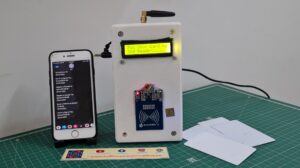
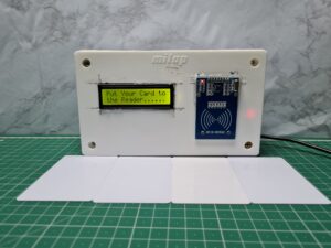
- In this article, we create an attendance system using the RC522 RFID module and GSM technology. This system will allow you to efficiently track attendance in various settings such as schools, and offices.
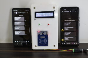
- Here we used RFID technology with the Arduino platform, we can easily identify and record attendance data, and send SMS to parents using GSM in real-time. Let’s use the components and make the step-by-step to build this attendance system.
Components Required
S.N | Components | Quantity |
1 | Arduino Nano | 1 |
2 | RC-522 RFID Module | 1 |
3 | 16×2 LCD Display with I2C | 1 |
4 | GSM Module (SIM900a) | 1 |
5 | RED LED | 1 |
6 | GREEN LED | 1 |
7 | Zero PCB | 1 |
8 | USB cable (for programming the Arduino) | 1 |
Arduino Nano
- The Arduino Nano is a compact size microcontroller board based on the ATmega328P IC. It is part of the Arduino family of development boards with the popular Arduino environment. However, the Nano is small in size and is a total of 14 digital pins available and a total of 8 analogue pins available and also supports UART, SPI and I2C Communication.
ATmega328P microcontroller
- The clock speed of 16 MHz.
- The flash is memory 32KB for storing the program code
- The SRAM for 2KB of data storage
- The EEPROM of 1KB for non-volatile storage.
- The digital and analog input/output pins can be used to interface with sensors, actuators, and other electronic components. It totals 14 digital I/O pins & 8 analog input pins.
The supports
- UART (Universal Asynchronous Receiver&Transmitter)
- SPI (Serial Peripheral Interface),
- I2C (Inter-Integrated Circuit).
- These all are interfaces with other devices such as sensors, displays, and wireless modules.
RC-522 RFID Module
- RC522 – RFID Reader / Writer 13.56MHz with Cards Kit includes a 13.56MHz RF reader cum writer module that uses an RC522 IC and two S50 RFID cards.
- The MF RC522 is a highly integrated transmission module for contactless communication at 13.56 MHz. RC522 supports ISO 14443A/MIFARE mode.
Key Features
- Operating Frequency: The RC522 module operates at a frequency of 13.56 MHz, which is the standard frequency for many RFID systems.
- SPI Interface: The RC522 module communicates with a microcontroller (such as Arduino) using the Serial Peripheral Interface (SPI) protocol.
RFID TAG
-
- The RC522 RFID tag, also known as an RFID card or transponder, is a small electronic device that contains a unique identification number or data. It is designed to be read by an RFID reader, such as the RC522 module, which uses radio frequency signals to communicate with the tag.
- Unique Identification- Each RC522 RFID tag has a unique identification number, which is typically pre-programmed to the tag during manufacturing.
GSM SIM900A
The SIM900 GSM/GPRS module is a versatile communication module that allows devices to connect to the Global System for Mobile Communications (GSM) network and transmit data over the General Packet Radio Service (GPRS).
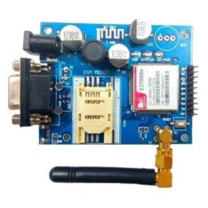
Key Features
- Quad-Band Operation: The SIM900A module supports quad-band operation, which means it can operate on four different GSM frequency bands: 850 MHz, 900 MHz, 1800 MHz, and 1900 MHz. This feature ensures compatibility with GSM networks worldwide.
- Communication Interfaces: The module offers various communication interfaces to interact with external devices. It typically includes UART (Universal Asynchronous Receiver-Transmitter) for serial communication with microcontrollers like Arduino.
16×2 LCD Display
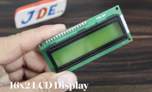
- A 16×2 LCD is a liquid crystal display that can display 16 characters in two rows.
- The “16×2” notation indicates the number of character positions available on the display.
- The I2C (Inter-Integrated Circuit) interface is a communication protocol that allows for easy and efficient communication between microcontrollers and peripheral devices.
When an LCD is connected using the I2C interface, it typically requires fewer pins compared to a direct parallel connection, making it more convenient for projects with limited available pins on the microcontroller.
- I2C Interface: The I2C interface uses a master-slave communication protocol.
Circuit Diagram
Source Code
- Upload the code to the Arduino Nano using the Arduino IDE.
- Test the system by scanning RFID tags and verifying if the attendance information is displayed on the LCD.
Necessary library
|
1 2 3 4 5 6 7 8 9 10 11 12 13 14 15 16 17 18 19 20 21 22 23 24 25 26 27 28 29 30 31 32 33 34 35 36 37 38 39 40 41 42 43 44 45 46 47 48 49 50 51 52 53 54 55 56 57 58 59 60 61 62 63 64 65 |
//Prateek //www.justdoelectronics.com #include <SPI.h> #include <MFRC522.h> #include <SoftwareSerial.h> #include <Wire.h> #include <DS3231.h> #include <LiquidCrystal_I2C.h> LiquidCrystal_I2C lcd(0x27, 16, 2); SoftwareSerial sim(2, 3); DS3231 rtc(SDA, SCL); const int checkInHour = 11; const int checkInMinute = 50; int userCheckInHour; int userCheckInMinute; String number = "+91xxxxxxxxxx"; String number1 = "+91xxxxxxxxxx"; String number2 = "+91xxxxxxxxxx"; String number3 = "+91xxxxxxxxxx"; String number4 = "+91xxxxxxxxxx"; int state1 = 0; int state2 = 0; int state3 = 0; int state4 = 0; int state5 = 0; #define buzzerPin A1 #define yellow 5 #define green 6 #define RST_PIN 4 #define SDA_PIN 10 MFRC522 mfrc522(SDA_PIN, RST_PIN); void setup() { lcd.init(); lcd.backlight(); lcd.setCursor(0, 0); Serial.begin(9600); sim.begin(9600); SPI.begin(); mfrc522.PCD_Init(); rtc.begin(); pinMode(buzzerPin, OUTPUT); pinMode(yellow, OUTPUT); pinMode(green, OUTPUT); lcd.setCursor(0, 0); lcd.print(" WELCOME "); lcd.setCursor(0, 1); lcd.print("TO OUR PROJECT"); delay(4000); lcd.clear(); } void loop() { RTC(); rfid(); } |
RTC()
|
1 2 3 4 5 6 7 8 9 10 11 12 13 14 15 16 17 18 19 20 21 |
void RTC() { //rtc.setDOW(WEDNESDAY); // Set Day-of-Week to SUNDAY //rtc.setTime(12, 43, 38); // Set the time to 12:00:00 (24hr format) //rtc.setDate(29, 4, 2022); // Set the date to January 1st, 2014 lcd.init(); lcd.backlight(); lcd.setCursor(0, 0); lcd.print("Put Your Card to"); lcd.setCursor(0, 1); lcd.print("the Reader......"); delay(700); lcd.clear(); lcd.setCursor(0, 0); lcd.print("Time: "); lcd.print(rtc.getTimeStr()); lcd.setCursor(0, 1); lcd.print("Date: "); lcd.print(rtc.getDateStr()); delay(500); lcd.clear(); } |
RFID()
|
1 2 3 4 5 6 7 8 9 10 11 12 13 14 15 16 17 18 19 20 21 22 23 24 25 26 27 28 29 30 31 32 33 34 35 36 37 38 39 40 41 42 43 44 45 46 47 48 49 50 51 52 53 54 55 56 57 58 59 60 61 62 63 64 65 66 67 68 69 70 71 72 73 74 75 76 77 78 79 80 81 82 83 84 85 86 87 88 89 90 91 92 93 94 95 96 97 98 99 100 101 102 103 104 105 106 107 108 109 110 111 112 113 114 115 116 117 118 119 120 121 122 123 124 125 126 127 128 129 130 131 132 133 134 135 136 137 138 139 140 141 142 143 144 145 146 147 148 149 150 151 152 153 154 155 156 157 158 159 160 161 162 163 164 165 166 167 168 169 170 171 172 173 174 175 176 177 178 179 180 181 182 183 184 185 186 187 188 189 190 191 192 193 194 195 196 197 198 199 200 201 202 203 204 205 206 207 208 209 210 211 212 213 214 215 216 217 218 219 220 221 222 223 224 225 226 227 228 229 230 231 232 233 234 235 236 237 238 239 240 241 242 243 244 245 246 247 248 249 250 251 252 253 254 255 256 257 258 259 260 261 262 263 264 265 266 267 268 269 270 271 272 273 274 275 276 277 278 279 280 281 282 283 284 285 286 287 288 289 290 291 292 293 294 295 296 297 298 299 300 301 302 |
void rfid() { if (!mfrc522.PICC_IsNewCardPresent()) { return; } if (!mfrc522.PICC_ReadCardSerial()) { return; } String content = ""; byte letter; for (byte i = 0; i < mfrc522.uid.size; i++) { Serial.print(mfrc522.uid.uidByte[i] < 0x10 ? " 0" : " "); Serial.print(mfrc522.uid.uidByte[i], HEX); content.concat(String(mfrc522.uid.uidByte[i] < 0x10 ? " 0" : " ")); content.concat(String(mfrc522.uid.uidByte[i], HEX)); } content.toUpperCase(); if (content.substring(1) == "14 AF DC 2B" && state1 == 0) { beepON(); lcd.clear(); lcd.setCursor(7, 0); lcd.print("Kevin"); lcd.setCursor(11, 1); lcd.print("001"); info(); digitalWrite(green, HIGH); delay(2000); digitalWrite(green, LOW); Message1(); state1 = 1; } else if (content.substring(1) == "14 AF DC 2B" && state1 == 1) { beepON(); lcd.clear(); lcd.setCursor(7, 0); lcd.print("Kevin"); lcd.setCursor(11, 1); lcd.print("001"); info(); digitalWrite(yellow, HIGH); delay(2000); digitalWrite(yellow, LOW); Message1(); state1 = 0; } else if (content.substring(1) == "92 09 DF E1" && state2 == 0) { beepON(); lcd.clear(); lcd.setCursor(7, 0); lcd.print("Darsh"); lcd.setCursor(11, 1); lcd.print("002"); info(); digitalWrite(green, HIGH); delay(2000); digitalWrite(green, LOW); Message2(); state2 = 1; } else if (content.substring(1) == "92 09 DF E1" && state2 == 1) { beepON(); lcd.clear(); lcd.setCursor(7, 0); lcd.print("Darsh"); lcd.setCursor(11, 1); lcd.print("002"); info(); digitalWrite(yellow, HIGH); delay(2000); digitalWrite(yellow, LOW); lcd.setCursor(11, 1); Message2(); state2 = 0; } else if (content.substring(1) == "20 9B EF 2F" && state3 == 0) { beepON(); lcd.clear(); lcd.setCursor(7, 0); lcd.print("Mohsin"); lcd.setCursor(11, 1); lcd.print("003"); info(); digitalWrite(green, HIGH); delay(2000); digitalWrite(green, LOW); Message3(); state3 = 1; } else if (content.substring(1) == "20 9B EF 2F" && state3 == 1) { beepON(); lcd.clear(); lcd.setCursor(7, 0); lcd.print("Mohsin"); lcd.setCursor(11, 1); lcd.print("003"); info(); digitalWrite(yellow, HIGH); delay(2000); digitalWrite(yellow, LOW); Message3(); state3 = 0; } else if (content.substring(1) == "F2 BC FD 44" && state4 == 0) { beepON(); lcd.clear(); lcd.setCursor(7, 0); lcd.print("Nagesh"); lcd.setCursor(11, 1); lcd.print("004"); info(); digitalWrite(green, HIGH); delay(2000); digitalWrite(green, LOW); Message4(); state4 = 1; } else if (content.substring(1) == "F2 BC FD 44" && state4 == 1) { beepON(); lcd.clear(); lcd.setCursor(7, 0); lcd.print("Nagesh"); lcd.setCursor(11, 1); lcd.print("004"); info(); digitalWrite(yellow, HIGH); delay(2000); digitalWrite(yellow, LOW); Message4(); state4 = 0; } else if (content.substring(1) == "92 09 DF E1" && state5 == 0) { beepON(); lcd.clear(); lcd.setCursor(7, 0); lcd.print("Prateek"); lcd.setCursor(11, 1); lcd.print("005"); info(); digitalWrite(green, HIGH); delay(2000); digitalWrite(green, LOW); Message5(); state5 = 1; } else if (content.substring(1) == "92 09 DF E1" && state5 == 1) { beepON(); lcd.clear(); lcd.setCursor(7, 0); lcd.print("Prateek"); lcd.setCursor(11, 1); lcd.print("005"); info(); digitalWrite(yellow, HIGH); delay(2000); digitalWrite(yellow, LOW); Message4(); state5 = 0; } else { digitalWrite(buzzerPin, HIGH); lcd.clear(); lcd.setCursor(0, 0); lcd.print("ID : "); lcd.print("Unknown"); lcd.setCursor(0, 1); lcd.print("Access denied"); Serial.println(" Access denied"); delay(1500); digitalWrite(buzzerPin, LOW); lcd.clear(); } } void smsSend() { lcd.setCursor(0, 0); lcd.print("SMS Sending"); for (int x = 11; x < 16; x++) { lcd.setCursor(x, 0); lcd.print("."); delay(1000); } } void beepON() { digitalWrite(buzzerPin, HIGH); delay(200); digitalWrite(buzzerPin, LOW); delay(100); } void info() { lcd.setCursor(0, 0); lcd.print("Name : "); lcd.setCursor(0, 1); lcd.print("Roll No : "); delay(1500); lcd.clear(); lcd.setCursor(0, 0); lcd.print("Authorized Access"); delay(1000); lcd.clear(); } void Message1() { lcd.setCursor(0, 0); lcd.print("SMS Sending"); sim.println("AT+CMGF=1"); delay(1000); sim.println("AT+CMGS=\"" + number + "\"\r"); delay(1000); if (state1 == 0) { const char message1[] = "Ram is Present at School "; sim.print(message1); } else if (state1 == 1) { const char message1[] = " Ram is Out Of The School"; sim.print(message1); } sim.println(rtc.getTimeStr()); sim.println(rtc.getDateStr()); delay(100); sim.println((char)26); smsSend(); } void Message2() { lcd.setCursor(0, 0); lcd.print("SMS Sending"); sim.println("AT+CMGF=1"); delay(1000); sim.println("AT+CMGS=\"" + number1 + "\"\r"); delay(1000); if (state2 == 0) { const char message2[] = "Rohan is Present at School"; sim.print(message2); } else if (state2 == 1) { const char message2[] = "Rohan is Out Of The School"; sim.print(message2); } sim.println(rtc.getTimeStr()); sim.println(rtc.getDateStr()); delay(100); sim.println((char)26); smsSend(); } void Message3() { lcd.setCursor(0, 0); lcd.print("SMS Sending"); sim.println("AT+CMGF=1"); delay(1000); sim.println("AT+CMGS=\"" + number2 + "\"\r"); delay(1000); if (state3 == 0) { const char message3[] = "Shyam is Present at School"; sim.print(message3); } else if (state3 == 1) { const char message3[] = "Shyam is Out Of The School"; sim.print(message3); } sim.println(rtc.getTimeStr()); sim.println(rtc.getDateStr()); delay(100); sim.println((char)26); smsSend(); } void Message4() { lcd.setCursor(0, 0); lcd.print("SMS Sending"); sim.println("AT+CMGF=1"); delay(1000); sim.println("AT+CMGS=\"" + number3 + "\"\r"); delay(1000); if (state4 == 0) { const char message4[] = "Sohan is Present at School"; sim.print(message4); } else if (state4 == 1) { const char message4[] = "Sohan is Out Of The School"; sim.print(message4); } sim.println(rtc.getTimeStr()); sim.println(rtc.getDateStr()); delay(100); sim.println((char)26); smsSend(); } void Message5() { lcd.setCursor(0, 0); lcd.print("SMS Sending"); sim.println("AT+CMGF=1"); delay(1000); sim.println("AT+CMGS=\"" + number4 + "\"\r"); delay(1000); if (state5 == 0) { const char message5[] = "Prateek is Present at School"; sim.print(message5); } else if (state5 == 1) { const char message5[] = "Prateek is Out Of The School"; sim.print(message5); } sim.println(rtc.getTimeStr()); sim.println(rtc.getDateStr()); delay(100); sim.println((char)26); smsSend(); } |
Project Demo
Video
More Arduino Tutorial
- Soil Moisture Sensor With Arduino
- DS18B20 Sensor With Arduino
- Water Level Sensor With Arduino
- Rain Sensor With Arduino
- BMP-180 Sensor With Arduino
Conclusion
- By combining the power of the RC522 RFID module, 16×2 LCD, Arduino Nano, and GSM technology, we have created an efficient attendance system capable of real-time monitoring. This system provides accurate attendance data that can be used for various applications.
- It is a versatile and cost-effective solution for organizations that require an automated attendance tracking system. Experiment with different features and enhancements to customize the system according to your specific needs.
