Introduction
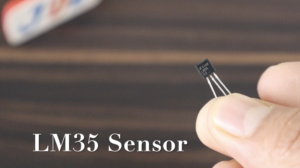
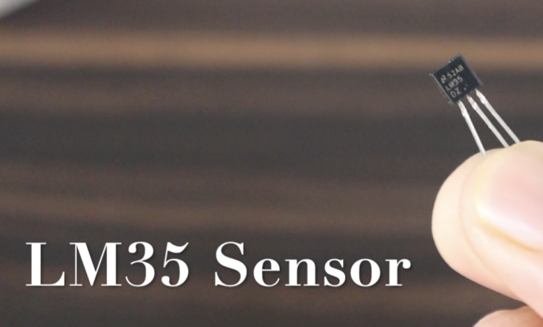
In this article, we discuss the LM35 temperature sensor. the lm35 sensor is analog sensor and its accuracy is good. we just interfaced the Lm35 sensor with Arduino and the reading will display in the serial monitor as well as 16×2 LCD Display and OLED Display.
The LM35 Sensor operating voltage range is 4v to 25v but we just interfaced with Arduino and given the 5v dc power source.
Calculation
LM35 temperature range is -55 °C To 150 °C
The max voltage is = 1500mv
The LM35 Sensor is a 10bit ADC and is 1024-bit (0-1023)
Let’s calculate Resolution = Vref / Step Size
Vref is Arduino Output Voltage = 5v
Step Size = 1024
- Operating Principle: The principle of temperature-dependent voltage output. It has a linear temperature characteristic.
- Temperature Range: Temperatures in the range of -55°C to +150°C. It has a wide operating temperature range.
- Output Voltage: It provides an analog output voltage directly proportional to the temperature it measures. The scale factor of 10 mV/°C.
- Accuracy: The LM35 sensor accuracy is ±0.5°C at room temperature.
Principle of Operation
- Temperature Sensing Element: At the heart of the LM35 sensor is a temperature-sensitive element, typically made of a solid-state material such as silicon. This element exhibits a linear change in electrical properties in response to temperature variations.
- Linear Voltage Output: Linear analog voltage output that is directly proportional to the temperature being measured. The output voltage has a scale factor of 10 mV/°C, meaning that for every degree Celsius rise in temperature, the output voltage increases by 10 mV.
- Sensor Calibration: This calibration process establishes the relationship between temperature and the corresponding output voltage.
- Supply Voltage: The range from 4V to 30V. It is important to provide a stable and appropriate supply voltage to ensure accurate temperature readings.
- Output Scaling: The output voltage of the LM35 sensor is linearly scaled to represent temperature. For example, at 25°C, the output voltage of the sensor would be 250 mV, and at 50°C, it would be 500 mV. The voltage output increases or decreases linearly with temperature changes within the sensor’s operating range.
- Interfacing and Conversion: The analog voltage output from the LM35 sensor can be easily interfaced with microcontrollers, analog-to-digital converters (ADCs), or other electronic circuits. It can be directly connected to the input of an ADC to convert the analog voltage into a digital temperature reading for further processing and analysis.
Specifications of the LM35 Sensor
- -55°C to +150°C Temperature Range.
- The output voltage has a scale factor of 10 mV/°C, meaning the voltage increases by 10 mV for every degree Celsius rise in temperature.
- Calibration accuracy of ±0.5°C at room temperature. However, the accuracy can vary depending on factors such as power supply voltage, self-heating, and environmental conditions.
- 4V to 25V Power Supply Required.
- 60 µA Current Consumption.
- Self-Heating: The LM35 sensor has low self-heating characteristics, minimizing the impact of the sensor’s own temperature on the measured temperature.
Advantages of LM35 Sensor
- High Accuracy
- Linear Output
- Wide Temperature Range
- Low Power Consumption
- Easy Interfacing
Disadvantage of LM35 Sensor
- Non-Standard Output
- Sensitivity to Noise
Application of LM35 Sensor
- Temperature Monitoring and Control
- HVAC Systems
- Weather Stations
- Industrial Process Control
- Medical Equipment
- Home Automation
- Energy Management Systems
- Automotive Applications
Example With Arduino
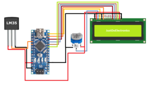
Circuit Diagram
Code
|
1 2 3 4 5 6 7 8 9 10 11 12 13 14 15 16 17 18 19 20 21 22 23 24 |
#define sensorPin A0 void setup() { Serial.begin(9600); } void loop() { int reading = analogRead(sensorPin); float voltage = reading * (5.0 / 1024.0); float temperatureC = voltage * 100; Serial.print("Temperature: "); Serial.print(temperatureC); Serial.print("\xC2\xB0"); Serial.print("C | "); float temperatureF = (temperatureC * 9.0 / 5.0) + 32.0; Serial.print(temperatureF); Serial.print("\xC2\xB0"); Serial.println("F"); delay(1000); } |
Code With 16×2 LCD Display
|
1 2 3 4 5 6 7 8 9 10 11 12 13 14 15 16 17 18 19 20 21 22 23 24 25 26 27 28 29 30 31 32 33 34 35 36 37 38 39 |
#include <LiquidCrystal.h> LiquidCrystal lcd(12, 11, 10, 9, 8, 7); byte Degree[] = { B00111, B00101, B00111, B00000, B00000, B00000, B00000, B00000 }; #define sensorPin A0 void setup() { lcd.begin(16,2); lcd.createChar(0, Degree); } void loop() { int reading = analogRead(sensorPin); float voltage = reading * (5.0 / 1024.0); float temperatureC = voltage * 100; lcd.setCursor(0, 0); lcd.print("Temperature:"); lcd.setCursor(0, 1); lcd.print(temperatureC, 1); lcd.print("C "); float temperatureF = (temperatureC * 9.0 / 5.0) + 32.0; lcd.print(temperatureF, 1); lcd.print("F "); delay(1000); } |
Code With OLED Display
|
1 2 3 4 5 6 7 8 9 10 11 12 13 14 15 16 17 18 19 20 21 22 23 24 25 26 27 28 29 30 31 32 33 34 35 36 37 38 39 40 41 42 43 44 45 46 47 48 49 50 51 52 53 54 55 56 57 58 |
#include <Wire.h> #include <Adafruit_GFX.h> #include <Adafruit_SSD1306.h> #define SCREEN_WIDTH 128 #define SCREEN_HEIGHT 64 #define ADC_VREF_mV 5000.0 #define ADC_RESOLUTION 1024.0 #define PIN_LM35 A0 Adafruit_SSD1306 oled(SCREEN_WIDTH, SCREEN_HEIGHT, &Wire, -1); String tempString; void setup() { Serial.begin(9600); if (!oled.begin(SSD1306_SWITCHCAPVCC, 0x3C)) { Serial.println(F("SSD1306 allocation failed")); while (true) ; } delay(2000); oled.clearDisplay(); oled.setTextSize(2); oled.setTextColor(WHITE); oled.setCursor(0, 10); tempString.reserve(10); } void loop() { int adcVal = analogRead(PIN_LM35); float milliVolt = adcVal * (ADC_VREF_mV / ADC_RESOLUTION); float tempC = milliVolt / 10; tempString = String(tempC, 2); tempString += "°C"; Serial.println(tempString); oledDisplayCenter(tempString); } void oledDisplayCenter(String text) { int16_t x1; int16_t y1; uint16_t width; uint16_t height; oled.getTextBounds(text, 0, 0, &x1, &y1, &width, &height); oled.clearDisplay(); oled.setCursor((SCREEN_WIDTH - width) / 2, (SCREEN_HEIGHT - height) / 2); oled.println(text); oled.display(); } |
LM35 Sensor Interfacing With Arduino And Blutooth App
Circuit Diagram
Code
|
1 2 3 4 5 6 7 8 9 10 11 12 13 14 15 16 17 18 19 20 21 22 23 24 25 26 27 28 29 30 31 32 33 34 35 36 37 38 |
#include <SoftwareSerial.h> SoftwareSerial mySerial(8, 9); int tempPin = A0; int read_ADC = 0; double temp = 0; double tempC = 0; double tempF = 0; void setup() { Serial.begin(9600); mySerial.begin(9600); Serial.println("Ready"); mySerial.println("Ready"); pinMode(tempPin, INPUT); for (int i = 0; i > -60; i -= 1) { } } void loop() { read_ADC = 0; for (int i = 0; i < 100; i++) { read_ADC = read_ADC + analogRead(tempPin); delay(1); } read_ADC = read_ADC / 100; temp = (read_ADC / 1023.0) * 5000; tempC = temp * 0.1; tempF = (tempC * 1.8) + 32; mySerial.print("S"); mySerial.print(";"); mySerial.print(tempC, 0); mySerial.print(";"); mySerial.print(tempF, 0); mySerial.println(";"); delay(10000); } |
LM35 Sensor Interfacing With Arduino And GSM
Circuit Diagram
Code
|
1 2 3 4 5 6 7 8 9 10 11 12 13 14 15 16 17 18 19 20 21 22 23 24 25 26 27 28 29 30 31 32 33 34 35 36 37 38 39 40 41 42 43 44 45 46 47 48 49 50 51 52 53 54 55 56 57 58 59 60 61 62 63 64 65 66 67 68 69 70 71 72 73 74 75 76 77 |
#include <LiquidCrystal_I2C.h> LiquidCrystal_I2C lcd(0x27, 20, 4); #include <SoftwareSerial.h> SoftwareSerial mySerial(7, 6); const int Buzzer = 3; const int LED_GREEN = 5; const int RELAY = 4; const int up_key = 8; const int down_key = 7; int SetPoint = 35; void setup() { mySerial.begin(9600); Serial.begin(9600); pinMode(Buzzer, OUTPUT); pinMode(LED_GREEN, OUTPUT); pinMode(RELAY, OUTPUT); pinMode(up_key, INPUT); pinMode(down_key, INPUT); digitalWrite(up_key, HIGH); digitalWrite(down_key, HIGH); lcd.init(); lcd.backlight(); lcd.setCursor(2, 0); lcd.print("WELCOME TO "); lcd.setCursor(2, 1); lcd.print("JUSTDOELECTRONICS"); lcd.setCursor(6, 2); lcd.print("DESIGN By :-"); lcd.setCursor(6, 3); lcd.print("PRATEEK"); delay(3000); lcd.clear(); digitalWrite(LED_GREEN, HIGH); digitalWrite(Buzzer, LOW); digitalWrite(RELAY, LOW); delay(2000); } void loop() { double Temperature = ((5.0 / 1024.0) * analogRead(A0)) * 100; lcd.setCursor(1, 0); lcd.print("Temperature:"); lcd.print(Temperature); if (digitalRead(down_key) == LOW) { if (SetPoint > 0) { SetPoint--; } } if (digitalRead(up_key) == LOW) { if (SetPoint < 150) { SetPoint++; } } lcd.setCursor(2, 1); lcd.print("Set Point:"); lcd.print(SetPoint); lcd.print("C "); if (Temperature < SetPoint) { digitalWrite(RELAY, LOW); digitalWrite(Buzzer, LOW); digitalWrite(LED_GREEN, HIGH); lcd.setCursor(1, 2); lcd.print("Exhaust fan :-OFF"); } else { digitalWrite(RELAY, HIGH); digitalWrite(LED_GREEN, LOW); digitalWrite(Buzzer, HIGH); lcd.setCursor(1, 2); lcd.print("Exhaust fan :- ON"); } delay(100); } |
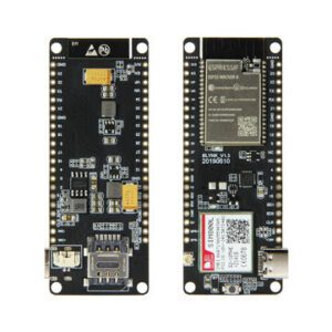
LM35 Sensor Interfacing With Lilygo Board
Lilygo Board Front And Back Image
Circuit Diagram
Video
Conclusion
- In this article, we interface with the LM35 sensor the response time of the sensor is good we will try with the Arduino, ESP01, ESP8266 And ESP32 microcontrollers. if you want a good response time then we suggest you used the LM35 sensor to measure the temperature.
If You are Interested In More Projects Then Plz Check Out
