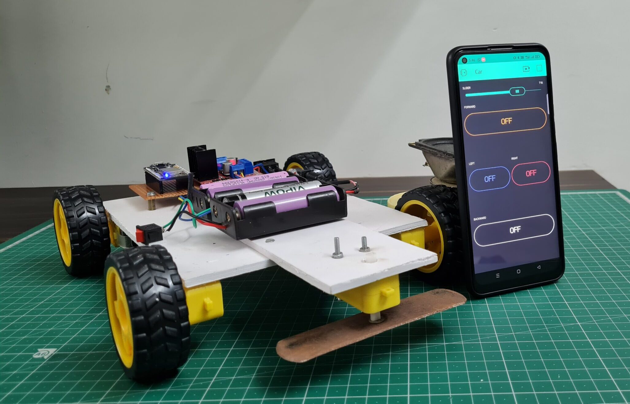
Grass Cutting Robot With ESP8266
grass cutting robot using ESP8266 with new Blynk app
Introduction
Hi everyone, welcome to JustDoElectronics.in this project, we build a grass-cutting robot using the Blynk app. the robot cuts the grass in a garden we control the Robot With New Blynk App.
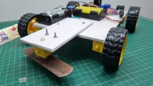
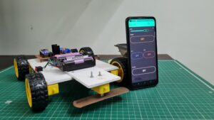
When you press the forward button the robot goes forward, the Same as backward, right and left. also, we hold the cutting blade in front of the robot.
we also provide a basic overview of the project and we provide all the details step by step.
If You are interested in More Projects Plz Check it out Here
Bill Of Materials
S.N | Component's | Quantity | Link To Buy |
1 | ESP8266 | 1 | |
2 | L298N Motor Driver | 1 | |
3 | Bo Motor | 4 | |
4 | Bo Motor Wheels | 4 | |
5 | Cutter Blade | 1 | |
6 | Relay Module | 1 | |
7 | 3.7 lithium battery | 1 |
ESP8266
L298N Motor Driver
The L298N Dual H-Bridge motor driver is a low-cost motor driver board in the market .that can drive 4 motors it uses the popular L298N dual H-Bridge Motor Driver chip & is also powerful enough to drive motors from 5-35 volts at 2 amps per channel.
This Board provides a handy 5V Regulator that can be used to power another circuit such as ESP8266, Arduino or another Mico-controller.
Features –
- Dual H-Bridge Motor driver Chip L298N
- 5V Regulator Poer Source
- Easy to interface with the most robot controller
- Drives motor from 5-35 at up to 2A Per circuit.
Specification –
- Input Voltage – 5-35v
- Output Current – 2A Per Channel
- Control Logic – Standard 5V TTL
- Power Consumption – 30ma For Logic
BO Motor
- This Bo motor Operates from 3-12V And Provides an impressive torque of 49 oz- in at just 5V.
- The Current consumes 40mA at 5V When free running at 24 rounds per min.
- The shaft on the Motor Is 7mm.
- The Gear motor Has a 224:1 Gear ratio with a 90-degree output Shaft.
Cutting Blade
Relay Module
The 1 Channel 5V Relay Module provides a single relay that can be controlled by any 5V digital output from your ESP8266.
- Connect the Signal (S) pin to a digital output line on your ESP8266 microcontroller.
- The Voltage (V) pin to a 5V operating voltage and the Ground (G) pin to a common ground.
- On the Output side Normally Open (NO), Normally Closed (NC) and Common (COM) screw terminals.
- When the digital Signal (S) pin is HIGH, the relay will be switched on (closed), otherwise, it will be switched off (opened).
How do They work?
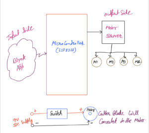
This is a robotic device designed to control the grass and maintain a lawn, these robots use the L298N Motor driver to control all 4 Bo motors we use the Blynk app and the robot will config to the wifi through.
This type of robot is required in the house to maintain the garden and the grass. This type of robot become the most popular in recent years to save time And man’s effort to maintain a lawn.
The Robots are usually equipped with a cutting machine which can be a reel of cutting blades or we used rotary blades. just adjusted the cutting height and motor we feet the sharp blade to cut the grass.
Robots cutting grass on a lawn can save time effort and energy compared to manual lawn moving and can help the good and maintain the lawn.
Blynk App
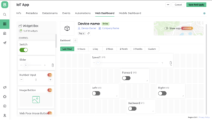
First, you have to set up a project in the Blynk app on your web dashboard and smartphone. after setting the app you receive an auth token which has to be provided in the code.
You can Download the Blynk app from Below the Links.
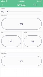
Open the Blynk App, register with an email ID and then log in. After logging in, we will create a project. Enter the all details as shown Below
Mobile App


Circuit Diagram
A Circuit Diagram of a Grass Cutting Robot using ESP8266 Board. would Show the connections Between the different components of the robot.
Ok, The L298N Motor Driver is Connected to the ESP8266 board. the 4 Bo motors are connected to the motor Driver Which is controlled via digital PWM Pins D0, D1, D2, D3, D4 And D5 of the ESP8266 Board.
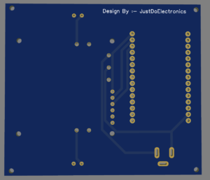
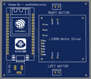
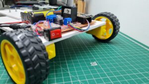
- Now we converting the circuit diagram into proper PCB. Here I used the EasyEDA Software To Design A PCB.
- Just Put The Module In The PCB Slots Like Esp8266 And L298N Motor Driver Module.
Source Code
The Source Code of the Grass cutting robot is Written in Arduino IDE software.
Before You Uploading The Code First Change a few Things.
- Auth
- ssid
- Pass
|
1 2 3 |
char auth[] = "OaAek11MGCAZQwBTyr1lPNLsHhyrG8"; char ssid[] = "Prateek"; char pass[] = "12345"; |
|
1 2 3 4 5 6 7 8 9 10 11 12 13 14 15 16 17 18 19 20 21 22 23 24 25 26 27 28 29 30 31 32 33 34 35 36 37 38 39 40 41 42 43 44 45 46 47 48 49 50 51 52 53 54 55 56 57 58 59 60 61 62 63 64 65 66 67 68 69 70 71 72 73 74 75 76 77 78 79 80 81 82 83 84 85 86 87 88 89 90 91 92 93 94 95 96 97 98 99 100 101 102 103 104 105 106 107 108 109 110 111 112 113 114 115 |
#define BLYNK_PRINT Serial #include <ESP8266WiFi.h> #include <BlynkSimpleEsp8266.h> //Motor PINs #define ENA D0 #define IN1 D1 #define IN2 D2 #define IN3 D3 #define IN4 D4 #define ENB D5 bool forward = 0; bool backward = 0; bool left = 0; bool right = 0; int Speed; char auth[] = "OaAek11MGCAZQwBTyr1lPNLsHhyrG8"; char ssid[] = "Prateek"; char pass[] = "12345"; void setup() { Serial.begin(9600); pinMode(ENA, OUTPUT); pinMode(IN1, OUTPUT); pinMode(IN2, OUTPUT); pinMode(IN3, OUTPUT); pinMode(IN4, OUTPUT); pinMode(ENB, OUTPUT); Blynk.begin(auth, ssid, pass, "blynk.cloud", 80); } BLYNK_WRITE(V0) { forward = param.asInt(); } BLYNK_WRITE(V1) { backward = param.asInt(); } BLYNK_WRITE(V2) { left = param.asInt(); } BLYNK_WRITE(V3) { right = param.asInt(); } BLYNK_WRITE(V5) { Speed = param.asInt(); } void smartcar() { if (forward == 1) { carforward(); Serial.println("carforward"); } else if (backward == 1) { carbackward(); Serial.println("carbackward"); } else if (left == 1) { carturnleft(); Serial.println("carfleft"); } else if (right == 1) { carturnright(); Serial.println("carright"); } else if (forward == 0 && backward == 0 && left == 0 && right == 0) { carStop(); Serial.println("carstop"); } } void loop() { Blynk.run(); smartcar(); } void carforward() { analogWrite(ENA, Speed); analogWrite(ENB, Speed); digitalWrite(IN1, LOW); digitalWrite(IN2, HIGH); digitalWrite(IN3, HIGH); digitalWrite(IN4, LOW); } void carbackward() { analogWrite(ENA, Speed); analogWrite(ENB, Speed); digitalWrite(IN1, HIGH); digitalWrite(IN2, LOW); digitalWrite(IN3, LOW); digitalWrite(IN4, HIGH); } void carturnleft() { analogWrite(ENA, Speed); analogWrite(ENB, Speed); digitalWrite(IN1, HIGH); digitalWrite(IN2, LOW); digitalWrite(IN3, HIGH); digitalWrite(IN4, LOW); } void carturnright() { analogWrite(ENA, Speed); analogWrite(ENB, Speed); digitalWrite(IN1, LOW); digitalWrite(IN2, HIGH); digitalWrite(IN3, LOW); digitalWrite(IN4, HIGH); } void carStop() { digitalWrite(IN1, LOW); digitalWrite(IN2, LOW); digitalWrite(IN3, LOW); digitalWrite(IN4, LOW); } |
Project Demo













how to connect details,can share ?