Introduction
Home automation has gained significant popularity due to its ability to enhance convenience and control over household appliances. In this project report, we present a home automation system based on Arduino Uno, four push buttons, a 5V 4-channel relay module, and a SIM800L GSM module. The system allows users to remotely control their home appliances using Dual-Tone Multi-Frequency (DTMF) signals through SMS, providing a seamless and user-friendly interface for home automation.
Components Needed
- Arduino Uno
- 4xPush Button
- 4xRelay Module
- SIM800L GSM Module
- LM2596 step down conveter
- Zero PCB
- Antenna
Arduino Uno
Arduino Uno is a popular microcontroller board that is part of the Arduino family. It is widely used in various electronic projects and prototyping due to its simplicity and versatility. Here’s an explanation of the Arduino Uno
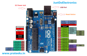
- The Arduino Uno is built around the Atmega328P microcontroller. This microcontroller has 32KB of flash memory, 2KB of SRAM, and 1KB of EEPROM. It operates at a clock speed of 16 MHz, providing enough processing power for most projects.
- The Arduino Uno features a total of 14 digital input/output pins, marked as D0 to D13. These pins can be configured as either inputs or outputs, allowing you to connect various sensors, actuators, and other digital devices. Additionally, 6 of these pins (D3, D5, D6, D9, D10, and D11) also support Pulse Width Modulation (PWM), enabling you to generate analogue-like outputs.
- The board also includes 6 analog input pins (A0 to A5), which can measure voltage levels ranging from 0 to 5 volts. These pins are useful for interfacing with analog sensors or reading variable inputs.
4xPush Button
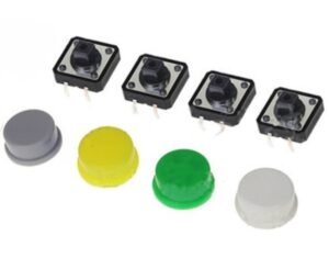
A push button is a simple electronic component that functions as a momentary switch. When pressed, it completes an electrical circuit, allowing current to flow temporarily.
- A push button is designed to provide a tactile input for users to trigger actions or control electronic devices. It allows users to manually activate or deactivate a specific function by pressing and releasing the button.
- Push buttons can be either normally open (NO) or normally closed (NC). In the normally open configuration, the electrical contacts are not connected when the button is at rest, and they only make contact when the button is pressed. In the normally closed configuration, the contacts are connected when the button is at rest and open when the button is pressed.
- o use a push button in a circuit, one pin is connected to a voltage source (e.g., VCC) and the other pin is connected to an input pin of a microcontroller or other electronic device. When the button is pressed, it completes the circuit, and the microcontroller can detect the change in input state.
4 Channel Relay Module
A 4-channel relay module is a device that allows you to control multiple electrical circuits using low-power signals from a microcontroller or other control systems. Each channel on the relay module is independent and can switch on or off a separate electrical circuit.
- A relay is an electrically operated switch that uses an electromagnet to mechanically toggle the position of its contacts. It allows a low-power control signal to control a higher-power circuit, such as turning on or off a household appliance, motor, or lighting system.
- A 4-channel relay module consists of four individual relays integrated onto a single board. Each relay has a common (COM) terminal, a normally open (NO) terminal, and a normally closed (NC) terminal. The COM terminal is connected to the circuit you want to control, while the NO and NC terminals are the two possible positions of the relay contacts.
- The 4-channel relay module typically has two sets of pins: input control pins and output pins.
- Input Control Pins: These pins connect to the microcontroller or control system. Each relay channel has an input pin, usually labelled IN1, IN2, IN3, and IN4. To control a specific relay channel, you need to send a signal to its corresponding input pin.
- Output Pins: These pins connect to the circuit or device you want to control. Each relay channel has three output pins: NO, NC, and COM. The COM pin is common for all channels, while the NO and NC pins are specific to each relay channel.
- The input control pins of the relay module are usually compatible with TTL (Transistor-Transistor Logic) or CMOS (Complementary Metal-Oxide-Semiconductor) logic levels, commonly used by microcontrollers. Depending on the relay module, the input pins may be active HIGH or active LOW. Check the datasheet or documentation of your specific relay module to determine the logic level required to trigger the relays.
SIM800L GSM Module
GSM SIM800L is a popular module that enables communication over GSM (Global System for Mobile Communications) networks. It provides functionalities for making calls, sending and receiving SMS messages, and connecting to the internet.
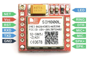
- The GSM SIM800L module is designed to work with GSM networks, allowing devices to establish communication through cellular networks. It operates on various frequencies and supports 2G,3G connectivity, making it compatible with most GSM networks worldwide.
- The module requires a power supply of around 3.7 to 4.2 volts. It can be powered using an external power source, such as a battery or a regulated power supply. It is important to ensure a stable power supply to ensure reliable operation.

- The module communicates with other devices, such as microcontrollers or computers, using serial communication. It typically utilizes UART (Universal Asynchronous Receiver-Transmitter) protocol, enabling devices to send and receive commands and data through serial communication.
Circuit Diagram
Source Code
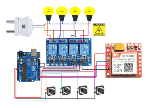
- Connect the VCC and GND pins of the Arduino Uno to the respective VCC and GND pins of the relay module.
- Establish a serial communication connection between the Arduino Uno and the GSM module.
- Connect each push button to a separate digital input pin on the Arduino Uno.
- Connect each relay module input pin to a digital output pin on the Arduino Uno.
- Connect the relay module output pins to the desired electrical appliances.
|
1 2 3 4 5 6 7 8 9 10 11 12 13 14 15 16 17 18 19 20 21 22 23 24 25 26 27 28 29 30 31 32 33 34 35 36 37 38 39 40 41 42 43 44 45 46 47 48 49 50 51 52 53 54 55 56 57 58 59 60 61 62 63 64 65 66 67 68 69 70 71 72 73 74 75 76 77 78 79 80 81 82 83 84 85 86 87 88 89 90 91 92 93 94 95 96 97 98 99 100 101 102 103 104 105 106 107 108 109 110 111 112 113 114 115 116 117 118 119 120 121 122 123 124 125 126 127 128 129 130 131 132 133 134 135 136 137 138 139 140 141 142 143 144 145 146 147 148 149 150 151 152 153 154 155 156 157 158 159 160 161 162 163 164 165 166 167 168 169 170 171 172 173 174 175 176 177 178 179 180 181 182 183 184 185 186 187 188 189 190 191 192 193 194 195 196 197 198 199 200 201 202 203 204 205 206 207 208 209 210 211 212 213 214 215 216 217 218 219 220 221 222 223 224 225 226 227 228 229 230 231 232 233 234 235 236 237 238 239 240 |
//Prateek //https://justdoelectronics.com //https://www.youtube.com/c/JustDoElectronics/videos #include <SoftwareSerial.h> #include "Adafruit_FONA.h" #define FONA_RX 2 #define FONA_TX 3 #define FONA_RST 4 const String PHONE = "+91xxxxxxxxxx"; String smsStatus, senderNumber, receivedDate, msg, buff; boolean isReply = false; String dtmf_cmd; boolean is_call = false; #define FONA_RI_INTERRUPT 0 SoftwareSerial fonaSS = SoftwareSerial(FONA_TX, FONA_RX); Adafruit_FONA fona = Adafruit_FONA(FONA_RST); #define button1_pin 4 #define button2_pin 5 #define button3_pin 6 #define button4_pin 7 #define relay1_pin 8 #define relay2_pin 9 #define relay3_pin 10 #define relay4_pin 11 boolean relay1_state = 1; boolean relay2_state = 1; boolean relay3_state = 1; boolean relay4_state = 1; void setup() { pinMode(button1_pin, INPUT); pinMode(button2_pin, INPUT); pinMode(button3_pin, INPUT); pinMode(button4_pin, INPUT); pinMode(relay1_pin, OUTPUT); pinMode(relay2_pin, OUTPUT); pinMode(relay3_pin, OUTPUT); pinMode(relay4_pin, OUTPUT); digitalWrite(relay1_pin, relay1_state); digitalWrite(relay2_pin, relay2_state); digitalWrite(relay3_pin, relay3_state); digitalWrite(relay4_pin, relay4_state); Serial.begin(115200); fonaSS.begin(9600); if (!fona.begin(fonaSS)) { Serial.println(F("Couldn't find FONA")); while (1) ; } Serial.println(F("FONA is OK")); fona.println("AT"); delay(500); fona.print("AT+CSMP=17,167,0,0\r"); fona.println("AT+DDET=1"); delay(500); smsStatus = ""; senderNumber = ""; receivedDate = ""; msg = ""; } void loop() { while (fona.available()) { buff = fona.readString(); handle_sim800_response(); } while (Serial.available()) { fona.println(Serial.readString()); } // listen_iir(); listen_push_buttons(); } void handle_sim800_response() { Serial.println(buff); if (is_call == true) { if (int index = buff.indexOf("+DTMF:") > -1) { index = buff.indexOf(":"); dtmf_cmd = buff.substring(index + 1, buff.length()); dtmf_cmd.trim(); Serial.println("dtmf_cmd: " + dtmf_cmd); if (dtmf_cmd == "1") control_relay(1); else if (dtmf_cmd == "2") control_relay(2); else if (dtmf_cmd == "3") control_relay(3); else if (dtmf_cmd == "4") control_relay(4); } if (buff.indexOf("NO CARRIER") > -1) { fona.println("ATH"); is_call = false; } } else if (buff.indexOf("RING") > -1) { delay(2000); fona.println("ATA"); is_call = true; } else if (buff.indexOf("+CMTI") > -1) { unsigned int index = buff.indexOf(","); String temp = buff.substring(index + 1, buff.length()); temp = "AT+CMGR=" + temp + "\r"; fona.println(temp); } else if (buff.indexOf("+CMGR") > -1) { extractSms(); if (msg == "1") control_relay(1); else if (msg == "2") control_relay(2); else if (msg == "3") control_relay(3); else if (msg == "4") control_relay(4); else if (msg.indexOf(".status") > -1) send_relay_status(msg.substring(0, 1)); else if (msg.indexOf("del all") > -1) delete_all_sms(); } } void extractSms() { unsigned int len, index; index = buff.indexOf("\r"); buff.remove(0, index + 2); buff.trim(); index = buff.indexOf(":"); buff.substring(0, index); buff.remove(0, index + 2); index = buff.indexOf(","); smsStatus = buff.substring(1, index - 1); buff.remove(0, index + 2); senderNumber = buff.substring(0, 13); buff.remove(0, 19); receivedDate = buff.substring(0, 20); buff.remove(0, buff.indexOf("\r")); buff.trim(); index = buff.indexOf("\n\r"); buff = buff.substring(0, index); buff.trim(); msg = buff; buff = ""; msg.toLowerCase(); } void listen_push_buttons() { if (digitalRead(button1_pin) == LOW) { delay(200); control_relay(1); } else if (digitalRead(button2_pin) == LOW) { delay(200); control_relay(2); } else if (digitalRead(button3_pin) == LOW) { delay(200); control_relay(3); } else if (digitalRead(button4_pin) == LOW) { delay(200); control_relay(4); } } void control_relay(int relay) { if (relay == 1) { relay1_state = !relay1_state; digitalWrite(relay1_pin, relay1_state); Serial.print("RelayState = "); Serial.println(relay1_state); delay(50); } else if (relay == 2) { relay2_state = !relay2_state; digitalWrite(relay2_pin, relay2_state); delay(50); } else if (relay == 3) { relay3_state = !relay3_state; digitalWrite(relay3_pin, relay3_state); delay(50); } else if (relay == 4) { relay4_state = !relay4_state; digitalWrite(relay4_pin, relay4_state); delay(50); } } void send_relay_status(String relay) { Serial.println("Relay Number: " + relay); //(relay1_state):"ON"?"OFF" String sms_text = ""; if (relay == "1") { sms_text = (relay1_state) ? "OFF" : "ON"; sms_text = "Relay 1 is " + sms_text; } else if (relay == "2") { sms_text = (relay2_state) ? "OFF" : "ON"; sms_text = "Relay 2 is " + sms_text; } else if (relay == "3") { sms_text = (relay3_state) ? "OFF" : "ON"; sms_text = "Relay 3 is " + sms_text; } else if (relay == "4") { sms_text = (relay4_state) ? "OFF" : "ON"; sms_text = "Relay 4 is " + sms_text; } Reply(sms_text); } void delete_all_sms() { fona.println("AT+CMGD=1,4"); delay(5000); while (fona.available()) { String response = fona.readString(); if (response.indexOf("OK") > -1) { Reply("All sms are deleted"); } else { Reply(response); } } } void Reply(String text) { Serial.println(text); fona.print("AT+CMGF=1\r"); delay(1000); fona.print("AT+CSMP=17,167,0,0\r"); fona.print("AT+CMGS=\"" + PHONE + "\"\r"); delay(1000); fona.print(text); delay(100); fona.write(0x1A); //sim800.println((char)26); delay(1000); Serial.println("SMS Sent Successfully."); msg = ""; } |
Video
Conclusion
With the help of Arduino Uno, a push button, a relay module, and a SIM800L GSM module, we can easily create a home automation system that allows remote control of appliances and provides status updates through SMS. This system enhances convenience, offers energy efficiency by remotely managing appliance usage, and improves security by notifying homeowners about the status of their home appliances. Experimenting and expanding upon this basic setup can lead to more advanced and personalized home automation solutions.
More Arduino Tutorial
