Digital Temperature Monitoring With DS18B20 Sensor & Arduino
Introduction
Temperature monitoring is essential in various applications, such as weather monitoring, industrial processes, and home automation. This article presents a digital temperature monitoring system that utilizes the DS18B20 temperature sensor, Arduino Nano microcontroller, and a 16×2 LCD display. The system provides an accurate and real-time display of temperature readings for easy monitoring and analysis.
- The Arduino Nano serves as the main controller for the temperature monitoring system. It is responsible for reading data from the DS18B20 sensor and displaying it on the LCD display.
- This digital sensor provides accurate temperature measurements with a resolution of up to 12 bits. It uses the one-wire communication protocol to transmit data to the Arduino Nano.
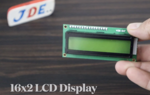
- The LCD display is used to visualize the temperature readings in a user-friendly format. It provides a two-line display with 16 characters per line, making it suitable for displaying temperature values.
Component Need
- Arduino Nano
- DS18B20 Temperature Sensor
- 16×2 LCD Display
- Buzzer
- USB cable (for programming the Arduino)
- Soldering wires
- Push Button
DS18B20 Temperature Sensor
The DS18B20 is a digital temperature sensor that provides accurate temperature readings with a resolution of up to 12 bits. It is a widely used sensor due to its simplicity, accuracy, and low cost. The sensor is capable of measuring temperatures ranging from -55°C to +125°C with an accuracy of ±0.5°C in the range of -10°C to +85°C.
Key Features
- One-Wire Interface: The DS18B20 sensor utilizes a one-wire communication protocol, which allows multiple sensors to be connected to a single microcontroller pin. This makes it convenient for applications that require multiple temperature measurements.
- Unique 64-Bit Address: Each DS18B20 sensor has a unique 64-bit address, which helps identify and communicate with individual sensors in a network. This feature is particularly useful when multiple sensors are connected to the same data line.
- Programmable Resolution: The DS18B20 sensor offers programmable resolution for temperature measurements. It can be configured to provide temperature readings with 9, 10, 11, or 12 bits of resolution, depending on the desired accuracy and response time.
- Parasitic Power Mode: The DS18B20 sensor supports parasitic power mode, which allows it to draw power from the data line during temperature measurements. This eliminates the need for an external power supply, simplifying the sensor’s wiring and reducing component count.
- Temperature Conversion Time: The sensor requires a specific amount of time to convert the analog temperature reading into a digital format. The conversion time varies depending on the resolution selected, with shorter conversion times for lower resolutions.
Applications
- Weather Monitoring: It is used to measure outdoor and indoor temperatures in weather stations, providing valuable data for weather analysis and prediction.
- Industrial Monitoring: The sensor is employed in industrial processes to monitor temperature variations in machinery, storage facilities, and other critical environments.
- Home Automation: DS18B20 sensors are used in smart home systems to control heating, ventilation, and air conditioning (HVAC) systems based on temperature measurements.
- Food and Beverage Industry: The sensor is utilized in food storage, refrigeration, and brewing processes to ensure proper temperature control and prevent spoilage.
- Medical Applications: DS18B20 sensors are used in medical devices and incubators to monitor and regulate temperatures for patient comfort and safety.
Arduino Nano
- The Arduino Nano is powered by the ATmega328P microcontroller chip, which is the same microcontroller used in the Arduino Uno board. The ATmega328P operates at a clock speed of 16 MHz and has 32KB of flash memory, 2KB of SRAM, and 1KB of EEPROM.
- The Nano is significantly smaller compared to other Arduino boards, measuring approximately 45mm x 18mm. It is designed in a compact DIP (Dual Inline Package) format, making it suitable for projects with space constraints or when a smaller form factor is required.
- The Arduino Nano provides a total of 14 digital I/O pins, of which 6 can be used for PWM (Pulse Width Modulation) output. It also offers 8 analog input pins, each of which can provide a 10-bit resolution. These pins allow you to interface with various sensors, actuators, and other electronic components.
16×2 LCD Display
- The 16×2 LCD display is rectangular in shape and typically measures around 80mm x 36mm. It usually consists of a backlit LCD screen, control circuitry, and a connection interface.
- The display has two rows, with each row capable of displaying up to 16 characters. The characters can be letters (both uppercase and lowercase), numbers, punctuation marks, symbols, and special characters.
- Many 16×2 LCD displays feature a built-in backlight, usually in the form of white or blue LEDs, to improve visibility in low-light conditions. The backlight can be controlled separately from the characters, allowing you to turn it on or off as needed.
- The LCD display module often includes an integrated controller, such as the commonly used HD44780 controller. The controller simplifies the interface with external devices by handling the low-level operations of displaying characters, managing the cursor position, and interpreting commands.
- The 16×2 LCD display can typically store and display custom-defined characters. These characters are created by defining a specific pattern of pixels and can be used to display icons, logos, or other specialized symbols beyond the standard character set.
Push Button
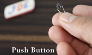
A 2-pin push button is a type of momentary switch that is commonly used in electronic circuits and systems. It consists of two electrical contacts and a spring-loaded button that, when pressed, establishes a temporary electrical connection between the two contacts. When the button is released, the connection is broken.
- Normally Open (NO) Contact: This pin is the common pin or the input pin. In its resting state (when the button is not pressed), there is no electrical connection between this pin and the other pin. When the button is pressed, the NO contact gets connected to the other pin, completing the circuit and allowing current to flow.
- Common (COM) Contact: This pin is connected to one end of the button. In its resting state, it is not electrically connected to the NO contact. When the button is pressed, the COM contact makes contact with the NO contact, establishing a temporary electrical connection.
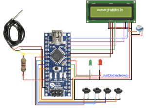
Circuit Diagram
DS18B20 Sensor Connection
-
- VCC: Connect to the 5V pin of the Arduino Nano.
- GND: Connect to the GND pin of the Arduino Nano.
- Data: Connect to an Analog pin (e.g., pin A0) of the Arduino Nano.
Code
|
1 2 3 4 5 6 7 8 9 10 11 12 13 14 15 16 17 18 19 20 21 22 23 24 25 26 27 28 29 30 31 32 33 34 35 36 37 38 39 40 41 42 43 44 45 46 47 48 49 50 51 52 53 54 55 56 57 58 59 60 61 62 63 64 65 66 67 68 69 70 71 72 73 74 75 76 77 78 79 80 81 82 83 84 85 86 87 88 89 90 91 92 93 94 95 96 97 98 99 100 101 102 103 104 105 106 107 108 109 110 111 112 113 114 115 116 117 118 119 120 121 122 123 124 125 126 127 128 129 130 131 132 133 134 135 136 137 138 139 140 141 142 143 144 145 146 147 148 149 150 151 152 153 154 155 156 157 158 159 160 161 162 163 164 165 166 167 168 169 170 171 172 173 174 175 176 177 178 179 180 181 182 183 184 185 186 |
#include <OneWire.h> #include <DallasTemperature.h> #include <LiquidCrystal.h> #include <EEPROM.h> LiquidCrystal lcd(12, 11, 10, 9, 8, 7); int add_chk = 0; int check_val = 3; int c_temp = 0; int c_temp_add = 1; int f_temp = 0; int f_temp_add = 2; int set = A3, dec = A4, inc = A5, stsp = A6; int numberOfDevices; int relay = 5; int buzzer = 6; int val_tol = 0; bool exit_stsp = false; bool exit_set = false; bool buz = true; bool re_heat = false; #define ONE_WIRE_BUS A0 #define TEMPERATURE_PRECISION 12 OneWire oneWire(ONE_WIRE_BUS); DallasTemperature sensors(&oneWire); DeviceAddress tempDeviceAddress; const int tol = 3; void setup(void) { lcd.begin(16, 2); sensors.begin(); pinMode(stsp, INPUT_PULLUP); pinMode(inc, INPUT_PULLUP); pinMode(dec, INPUT_PULLUP); pinMode(set, INPUT_PULLUP); pinMode(relay, OUTPUT); pinMode(buzzer, OUTPUT); digitalWrite(relay, LOW); digitalWrite(buzzer, LOW); lcd.clear(); lcd.setCursor(0, 0); lcd.print(" Temperature "); lcd.setCursor(0, 1); lcd.print(" Controller"); numberOfDevices = sensors.getDeviceCount(); if (EEPROM.read(add_chk) != check_val) { EEPROM.write(add_chk, check_val); EEPROM.write(c_temp_add, 50); f_temp = f_conv(50); EEPROM.write(f_temp_add, f_temp); c_temp = EEPROM.read(c_temp_add); f_temp = EEPROM.read(f_temp_add); } else { c_temp = EEPROM.read(c_temp_add); f_temp = EEPROM.read(f_temp_add); } delay(1500); } void loop(void) { lcd.setCursor(0, 0); lcd.print("PRESS START/SET"); lcd.setCursor(0, 1); lcd.print("TEMP: "); lcd.print(EEPROM.read(c_temp_add)); lcd.print("C/"); lcd.print(EEPROM.read(f_temp_add)); lcd.print("F"); if (digitalRead(set) == LOW && exit_set == false) { exit_set = true; c_temp = EEPROM.read(c_temp_add); f_temp = EEPROM.read(f_temp_add); while (exit_set) { if (digitalRead(inc) == LOW) { c_temp += 1; if (c_temp > 110) c_temp = 0; f_temp = f_conv(c_temp); delay(50); } if (digitalRead(dec) == LOW) { c_temp -= 1; if (c_temp < 0) c_temp = 110; f_temp = f_conv(c_temp); delay(50); } lcd.clear(); lcd.setCursor(0, 0); lcd.print("SET TEMPERATURE:"); lcd.setCursor(0, 1); lcd.print(" "); lcd.print(c_temp); lcd.print("C/"); lcd.print(f_temp); lcd.print("F"); delay(150); if (digitalRead(set) == LOW) { delay(500); if (digitalRead(set) == LOW) { exit_set = false; if (EEPROM.read(c_temp_add) == c_temp) { lcd.clear(); lcd.print("VALUE UNCHANGED!"); delay(1500); } else { EEPROM.write(c_temp_add, c_temp); EEPROM.write(f_temp_add, f_temp); lcd.clear(); lcd.print(" VALUE SAVED!"); lcd.setCursor(0, 1); lcd.print("****************"); delay(1500); lcd.clear(); } } } } } if (digitalRead(stsp) == LOW && exit_stsp == false) { exit_stsp = true; lcd.clear(); lcd.setCursor(0, 0); lcd.print("SET: "); lcd.print(EEPROM.read(c_temp_add)); lcd.print("C/"); lcd.print(EEPROM.read(f_temp_add)); lcd.print("F"); buzz(); digitalWrite(relay, HIGH); while (exit_stsp) { sensors.requestTemperatures(); for (int i = 0; i < numberOfDevices; i++) { if (sensors.getAddress(tempDeviceAddress, i)) { printTemperature(tempDeviceAddress); } } lcd.setCursor(0, 1); lcd.print("TEMP: "); lcd.print(c_temp); lcd.print("C/"); lcd.print(f_temp); if (f_temp < 100) { lcd.print("F "); } else { lcd.print("F"); } if (c_temp >= EEPROM.read(c_temp_add) && buz == true) { delay(5000); if (c_temp >= EEPROM.read(c_temp_add)) { digitalWrite(relay, LOW); buz = false; re_heat = true; for (int j = 0; j < 15; j++) { digitalWrite(buzzer, HIGH); delay(100); digitalWrite(buzzer, LOW); delay(100); } } } val_tol = EEPROM.read(c_temp_add) - tol; if (c_temp <= val_tol && re_heat == true) { buz = true; re_heat = false; digitalWrite(relay, HIGH); } if (digitalRead(stsp) == LOW && exit_stsp == true) { delay(1500); if (digitalRead(stsp) == LOW) { digitalWrite(relay, LOW); exit_stsp = false; lcd.clear(); lcd.print("PROCESS STOPPED!"); lcd.setCursor(0, 1); lcd.print("****************"); buzz(); delay(500); lcd.clear(); break; } } } } } |
Video
More Arduino Tutorial
- Soil Moisture Sensor With Arduino
- DS18B20 Sensor With Arduino
- Water Level Sensor With Arduino
- Rain Sensor With Arduino
- BMP-180 Sensor With Arduino
Conclusion
The digital temperature monitoring system using the DS18B20 sensor, Arduino Nano, and 16×2 LCD display offers a reliable and cost-effective solution for monitoring temperature in various applications. It provides accurate temperature readings and displays them in a user-friendly format for easy interpretation. The system can be expanded and customized further based on specific requirements


