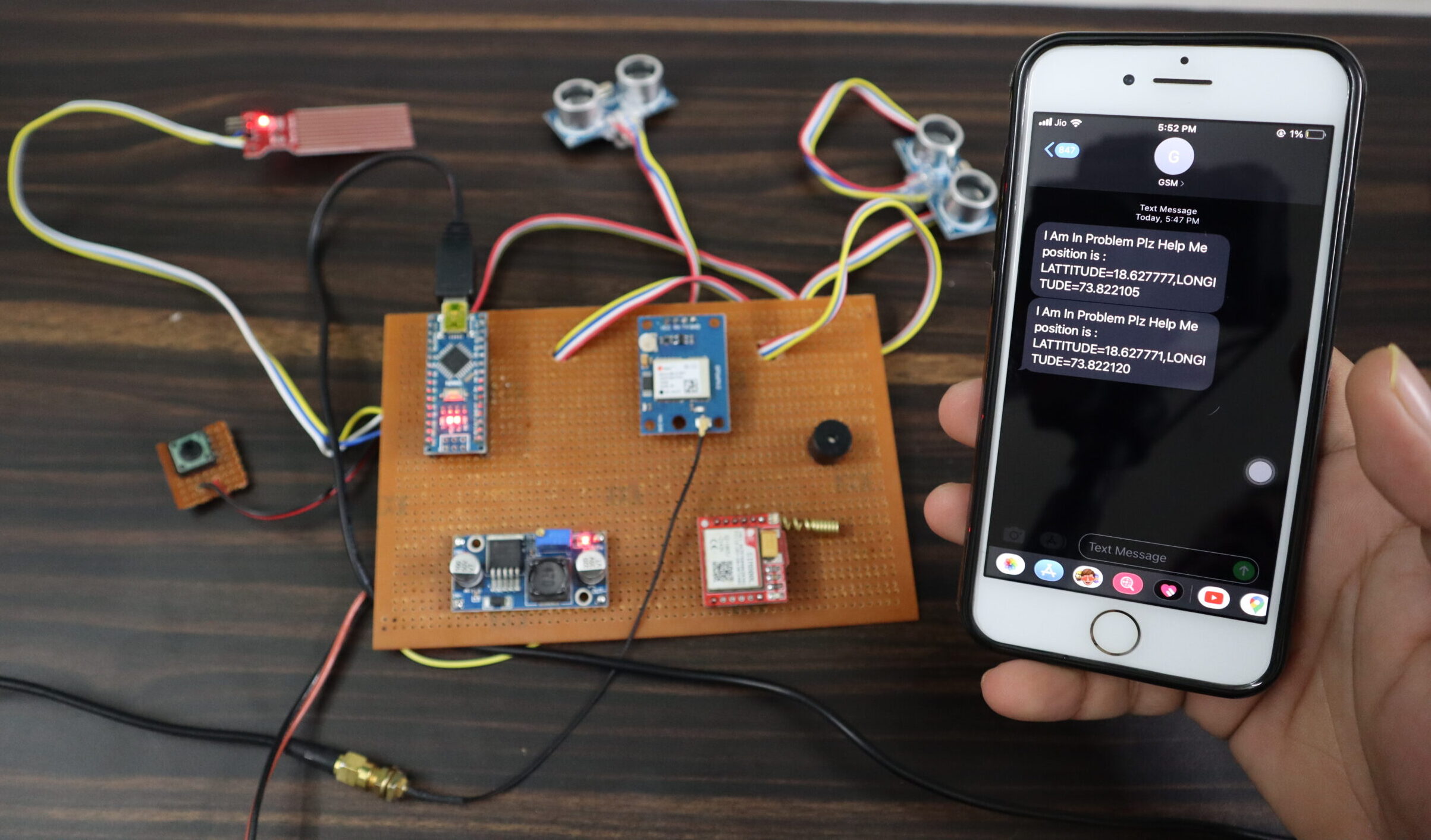
Arduino Based Blind Stick With GPS And GSM
step by step guide how you make your own blind stick with GPS And GSM
Introduction
Hi, Friends In this Blog You Learn All About Blind Stick Using GPS And GSM modules. I Will Explain All The Things In Detail about How the Project Will Work.
- The main problem Of Blind People Is how to navigate their way to wherever they want to go. that’s such people need to blind Stick.to find out the correct path.
- The blind people put the ultrasonic Sensor in a cap and then move. The ultrasonic sensor puts both sides front and back side, if the front ultrasonic sensor senses the obstacle the buzzer beeps which means it informs the Blind People is an obstacle in your front.
- if blind people move backside and back side ultrasonic sensor sense the obstacle that’s the time buzzer beeps in a different sound. then blind people listen to the sound and know the buzzer beep sound is easy to understand where is come obstacle.
- Now the blind people carry the stick I just put the water sensor on the downside of the stick. if stick goo in water they inform the blind people is some water is a downside and is easily understood. if blind people facing some problem then just press the push button that’s the time GSM Send the text message to the parent’s mobile number Or Police Station With a Proper GPS Location.
Bill Of Materials
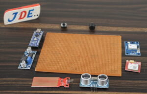
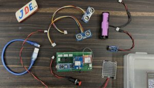
Here I put All the Component List That I Used In this Project
S.N | Components | Quanitity | Link To Buy |
1 | Arduino Nano | 1 | |
2 | GSM Sim800l Module | 1 | |
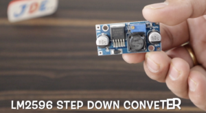
3 | LM2596 Step Down Conveter | 1 | |
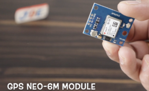
4 | GPS Neo-6m | 1 | |
5 | HC-SR 04 Ultersonic Sensor | 1 | |
6 | Water Sensor | 1 | |
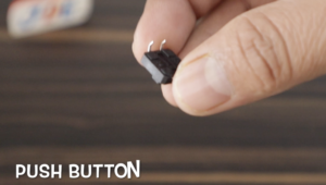
7 | Push Button | 1 | |
8 | Buzzer | 1 | |
9 | Zero PCB | 1 |
Hardware Part
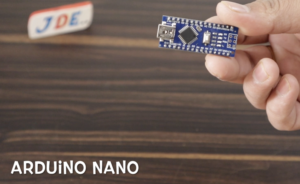
In This Project, I used the Arduino nano microcontroller Board Because is Small And is providing the Soo many pins.
Arduino Nano Board
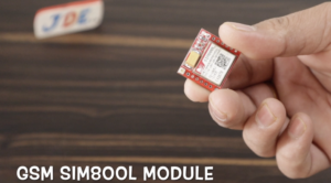
SIM800l Gsm module size is Also Small and Requires 3.7 volts only
- RX Pin-Connected To The D2 Pin
- Tx Pin-Connected To The D3 Pin
- LM2596 is a step-down converter that converts the 9v or 12v Dc Supply To 3.7 volts and GSM sim800l is required for the 3.7-volt Supply.
- GPS Neo-6m Module This is also in small size and they work on the 5v DC Supply
- RX Pin-Connected To The D10 Pin
- Tx Pin-Connected To The D11 Pin
- HC-sr04 Ultrasonic Sensor In this project I used 2 ultrasonic sensors that work on the 5v DC Supply
1. Ultrasonic Sensor
- Vcc 5v
- Echo A0 Pin
- Trig A1 Pin
- Gnd Gnd
2. Ultrasonic Sensor
- Vcc 5v
- Echo A2 Pin
- Trig A3 Pin
- Gnd Gnd
The water Sensor also works on 5v if water touches the sensor that’s time sensor signal is High
- VCC 5v
- Signal A4
- Gnd Gnd
- Push Button they Connected To The Pin Number D6
- The buzzer will be connected to the PIN D8
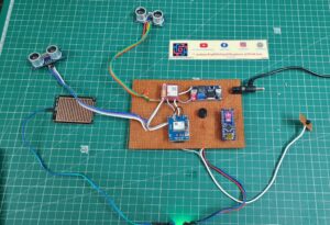
- In this Project we Used The 4×4 Zero PCB I soldered All The Components In The zero PCB.
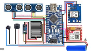
Circuit Diagram
This Circuit diagram I Make Of EasyEda Software If you want to make your Design just Visit The Site
With Buzzer
PCB Design
I hope You understand All The connections If you doubt anything Just Comment below on the blog I will try to explain them.
Source Code
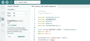
Before You upload the code just add the lib
Now Select the proper Board And upload the Code.
|
1 2 3 4 5 6 7 8 9 10 11 12 13 14 15 16 17 18 19 20 21 22 23 24 25 26 27 28 29 30 31 32 33 34 35 36 37 38 39 40 41 42 43 44 45 46 47 48 49 50 51 52 53 54 55 56 57 58 59 60 61 62 63 64 65 66 67 68 69 70 71 72 73 74 75 76 77 78 79 80 81 82 83 84 85 86 87 88 89 90 91 92 93 94 95 96 97 98 99 100 101 102 103 104 105 106 107 108 109 110 111 112 113 114 115 116 117 118 119 120 121 122 123 124 125 126 127 128 129 130 131 132 133 134 135 136 137 138 139 140 141 142 143 144 145 146 147 148 149 150 151 152 153 154 155 156 157 158 159 160 161 162 163 164 165 166 167 168 169 170 171 172 173 174 175 176 177 178 179 180 181 182 183 184 185 186 187 188 189 190 191 192 193 194 195 196 197 198 199 200 201 202 203 204 205 206 207 208 209 210 211 212 213 214 215 216 217 218 219 220 221 222 223 224 225 226 |
//Prateek //www.justdoelectronics.com //https://www.youtube.com/@JustDoElectronics #include <SoftwareSerial.h> #include <TinyGPS++.h> float lattitude, longitude; float a[2]; float *p; SoftwareSerial gpsSerial(2, 3); SoftwareSerial gsmSerial(10, 11); TinyGPSPlus gps; const int trigPin1 = A1; const int echoPin1 = A0; long duration1; int distance1; const int trigPin2 = A2; const int echoPin2 = A3; long duration2; int distance2; int buttonpin = 6; void setup() { pinMode(trigPin1, OUTPUT); pinMode(echoPin1, INPUT); pinMode(5, OUTPUT); pinMode(A4, INPUT_PULLUP); Serial.begin(9600); pinMode(trigPin2, OUTPUT); pinMode(echoPin2, INPUT); pinMode(buttonpin, INPUT_PULLUP); Serial.begin(9600); delay(1000); gpsSerial.begin(9600); delay(1000); gsmSerial.begin(9600); delay(1000); Serial.print("—Tracking–"); Serial.print("***Location***"); gsmSerial.println("AT+CNMI=2,2,0,0,0"); delay(3000); Serial.print("Initializing……"); delay(2000); Serial.print("System Ready "); delay(1000); } void loop() { digitalWrite(trigPin1, LOW); delayMicroseconds(2); digitalWrite(trigPin1, HIGH); delayMicroseconds(10); digitalWrite(trigPin1, LOW); duration1 = pulseIn(echoPin1, HIGH); distance1 = duration1 * 0.034 / 2; Serial.print("Distance1: "); Serial.println(distance1); digitalWrite(trigPin2, LOW); delayMicroseconds(2); digitalWrite(trigPin2, HIGH); delayMicroseconds(10); digitalWrite(trigPin2, LOW); duration2 = pulseIn(echoPin2, HIGH); distance2 = duration2 * 0.034 / 2; Serial.print("Distance2: "); Serial.println(distance2); if (distance1 <= 20 || distance2 <= 20) { //Prateek //www.justdoelectronics.com //https://www.youtube.com/@JustDoElectronics digitalWrite(5, HIGH); delay(1000); digitalWrite(5, LOW); digitalWrite(5, HIGH); delay(1000); digitalWrite(5, LOW); digitalWrite(5, HIGH); delay(1000); digitalWrite(5, LOW); } else if (distance1 <= 15 || distance2 <= 15) { digitalWrite(5, HIGH); delay(500); digitalWrite(5, LOW); digitalWrite(5, HIGH); delay(500); digitalWrite(5, LOW); digitalWrite(5, HIGH); delay(500); digitalWrite(5, LOW); } else digitalWrite(5, LOW); int sensorValue = digitalRead(A4); if (sensorValue == 1) { digitalWrite(5, HIGH); Serial.println("Rain Alert"); delay(1500); digitalWrite(5, LOW); digitalWrite(5, HIGH); delay(1500); } else digitalWrite(5, LOW); if (digitalRead(buttonpin) == LOW) { Serial.println("button pressed"); delay(2000); SendMessage(); } if (gsmSerial.available() > 0) Serial.write(gsmSerial.read()); while (gsmSerial.available()) { gsmSerial.read(); } while (Serial.available()) { Serial.read(); } get_gsm(); } float *get_gps() { gpsSerial.listen(); Serial.println("INSIDE get_gps"); while (1) { while (gpsSerial.available() > 0) { gps.encode(gpsSerial.read()); } if (gps.location.isUpdated()) { //Prateek //www.justdoelectronics.com //https://www.youtube.com/@JustDoElectronics Serial.print("LAT="); Serial.println(gps.location.lat(), 6); Serial.print("LONG="); Serial.println(gps.location.lng(), 6); lattitude = gps.location.lat(); longitude = gps.location.lng(); break; } } a[0] = lattitude; a[1] = longitude; return a; } void get_gsm() { gsmSerial.listen(); while (gsmSerial.available() > 0) //Prateek //www.justdoelectronics.com //https://www.youtube.com/@JustDoElectronics { Serial.println("INSIDE gsmSerial.available"); if (gsmSerial.find("Track")) { Serial.println("INSIDE track"); gsmSerial.println("AT+CMGF=1"); delay(1000); gsmSerial.println("AT+CMGS=\"+9188305848xx\"\r"); delay(1000); p = get_gps(); gsmSerial.listen(); Serial.print("Your Location: "); gsmSerial.print("Your Location: "); Serial.print("LATTITUDE="); Serial.print(*p, 6); gsmSerial.print("LATTITUDE="); gsmSerial.print(*p, 6); gsmSerial.print(","); Serial.print("LONGITUDE="); Serial.print(*(p + 1), 6); gsmSerial.print("LONGITUDE="); gsmSerial.print(*(p + 1), 6); delay(100); gsmSerial.println((char)26); delay(1000); } } } void SendMessage() { gsmSerial.println("AT+CMGF=1"); delay(1000); gsmSerial.println("AT+CMGS=\"+9188305848xx\"\r"); delay(1000); gsmSerial.println("I Am In Problem Plz Help Me"); delay(1000); p = get_gps(); gsmSerial.listen(); Serial.print("Your Position is : "); gsmSerial.print("position is : "); Serial.print("LATTITUDE="); Serial.print(*p, 6); gsmSerial.print("LATTITUDE="); gsmSerial.print(*p, 6); gsmSerial.print(","); Serial.print("LONGITUDE="); Serial.print(*(p + 1), 6); gsmSerial.print("LONGITUDE="); gsmSerial.print(*(p + 1), 6); delay(100); //Prateek //www.justdoelectronics.com //https://www.youtube.com/@JustDoElectronics gsmSerial.println((char)26); } |
- Now I have tested the code is working Properly you just change your mobile number
- Here You Put Your Mobile Number
|
1 2 3 |
gsmSerial.println("AT+CMGS=\"+9188305848xx\"\r"); delay(1000); gsmSerial.println("I Am In Problem Plz Help Me"); |
Project Demo
Video
Sensor






is it that we have to put sim for gsm
Can we use any type of gsm module? And can you say any easier alternatives for step down converter, pls say fast I have a competition
yes
can you please suggest us how to do this project using ESP32 . What major changes will be there? please let me know!
Thank you!