How To Make A DIY Arduino Joystick Control Car
How To Make A DIY Arduino Joystick Control Car At Home
Introduction
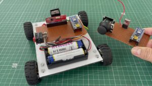
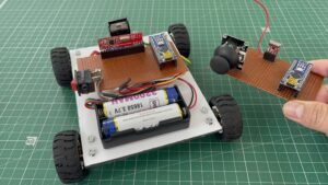
Hi Friend Welcome Back, In this Article, we designed an RF Small Robot car with the help of an Arduino microcontroller. We control the robot with the help of the PS2 Joystick Module.
We used The RF Transmitter And Receiver Module They Work On 433MHz Frequency.
This hybrid RF Transceiver Module provides a complete RF transmitter and receiver module solution which can be used to transmit data at up to 3KHz from any standard CMOS/TTL source.
why do we use a 433MHz RF Transmitter Receiver Module?
- Low Power Consumption
- Easy For RF-based Application
- Transmitter Transmit Range Up To 50m
- CMOS / TTL Input
- Very Stable Operating Frequency
- Low Current Consumption up to 11mA
- Wide Operating Voltage
- ASK Modulation
Check Out More Projects
Bill Of Material
S.N | Component's | Quantity | Link To Buy |
1 | Arduino Nano | 2 | |
2 | RF Transmitter & Reciver Module | 1 | |
3 | L298N Motor Driver | 1 | |
4 | N20 Motor | 4 | |
5 | N20 Motor Wheels | 4 | |
6 | 3.7V lithium ion Battery | 1 | |
7 | Zero PCB | 2 | |
8 | Soldring Wire | 20 | |
9 | Power Supply | 1 | |
10 | Conector | 1 |
Component’s
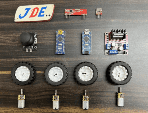
Here I used two Arduino one for the transmitter side and another one for the receiver side.
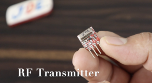
RF Transmitter is 4 Pin You just connect to VCC-5v, GND – GND and the DATA pin is conected to any digital pin in Arduino nano microcontroller.
In the RF Receiver module 4 pins on both sides right and left flow the circuit diagram and do the connection like VCC -5V, GND – GND and DATA Pin is conected to any digital pin Arduino Nano microcontroller.
L298N Motor is a Power full motor Driver working On a 9V-12V Power Supply.
N20 Gear Motor is a small-sized motor and is very powerful also the gear mechanism is a relay good and works on low voltage. In this project we used the 150rpm Motor you also changed in your requirements.
Here we used the 2 Lithium ion batteries Conected in series, which are proved near 8V DC and directly connected to the L298N Motor Driver.
Note:- Please Use only rechargeable batteries in this project
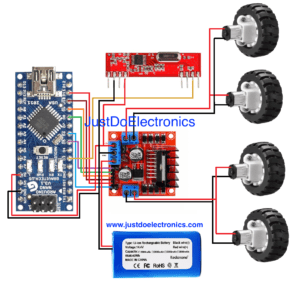
Circuit Diagram
Transmitter Circuit
We used the PS2 Joystick Module and RF Transmitter Module in the transmitter circuit.
- The PS2 Joystick Module is conected to the Analog Pin Vrx – A1, Vry – A2, VCC – 5V And GND To GND.
- RF Transmitter is conected to the Pin Number D12, VCC – 5V And GND To GND.
Receiver Circuit
In this Receiver Circuit Diagram, we used the L298N Motor Driver Module to control the Speed of the Motor.
- The RF receiver module is conected to the Pin Number D3, VCC – 5V, And GND to GND.
- L298N Motor Driver Module is conected to Pin Numbers D5, D8, D9, D10, D11 And D6.
- Here we used the N20 Motor Which is connected to the L298N Motor Driver Output Pins just flow the circuit Diagram.
Code
- Transmitter Code
|
1 2 3 4 5 6 7 8 9 10 11 12 13 14 15 16 17 18 19 20 21 22 23 24 25 26 27 28 29 30 31 32 33 34 35 36 37 38 39 40 41 42 43 44 45 46 47 48 49 50 51 52 53 54 55 56 57 58 59 60 61 62 63 64 65 66 67 68 69 70 71 72 73 74 75 76 77 78 79 80 |
//Prateek //www.justdoelectronics.com //https://www.youtube.com/@JustDoElectronics/videos //Transmitter #include <VirtualWire.h> const int transmit_pin = 12; String str; char cstr[100]; String message = ""; unsigned int mlength; int flag = 0; int buttonf = 0; int power = 7; int button = 4; int vrx = A2; int vry = A1; int xdata = 0; int ydata = 0; void setup() { vw_set_tx_pin(transmit_pin); vw_setup(2000); Serial.begin(9600); pinMode(vrx, INPUT); pinMode(vry, INPUT); pinMode(power, OUTPUT); digitalWrite(power, HIGH); pinMode(button, INPUT); digitalWrite(button, HIGH); } void loop() { control(); if (buttonf == 1) { xdata = analogRead(vrx); ydata = analogRead(vry); SendData(xdata, ydata, buttonf); } if (buttonf == 0) { SendData(0, 0, 0); delay(100); } } void SendData(int xvalue, int yvalue, int buttonstatus) { message = message + xvalue + "," + yvalue + "," + buttonstatus; mlength = message.length(); str = message; str.toCharArray(cstr, 100); vw_send((uint8_t *)cstr, mlength); vw_wait_tx(); str = ""; message = ""; } void control() { if ((digitalRead(button) == LOW) && (buttonf == 0)) { Serial.println(" Started"); buttonf = 1; delay(1000); } if ((digitalRead(button) == LOW) && (buttonf == 1)) { Serial.println("ended"); buttonf = 0; delay(1000); } digitalWrite(button, HIGH); } |
- Receiver Code
|
1 2 3 4 5 6 7 8 9 10 11 12 13 14 15 16 17 18 19 20 21 22 23 24 25 26 27 28 29 30 31 32 33 34 35 36 37 38 39 40 41 42 43 44 45 46 47 48 49 50 51 52 53 54 55 56 57 58 59 60 61 62 63 64 65 66 67 68 69 70 71 72 73 74 75 76 77 78 79 80 81 82 83 84 85 86 87 88 89 90 91 92 93 94 95 96 97 98 99 100 101 102 103 104 105 106 107 108 109 110 111 112 113 114 115 116 117 118 119 120 121 122 123 124 125 126 127 128 129 130 131 132 133 134 135 136 137 138 139 140 141 142 143 144 145 146 147 148 |
//Prateek //www.justdoelectronics.com //https://www.youtube.com/@JustDoElectronics/videos //Receiver #include <VirtualWire.h> const int receive_pin = 3; String message; String myString; int xvalue; int yvalue; int buttonf; int xdata; int ydata; int bfdata; int ena = 5; int enb = 6; int in1 = 8; int in2 = 9; int in3 = 10; int in4 = 11; void setup() { delay(1000); Serial.begin(9600); pinMode(ena, OUTPUT); pinMode(enb, OUTPUT); pinMode(in1, OUTPUT); pinMode(in2, OUTPUT); pinMode(in3, OUTPUT); pinMode(in4, OUTPUT); analogWrite(ena, 0); analogWrite(enb, 0); delay(1000); Serial.println("setup"); vw_set_rx_pin(receive_pin); vw_set_ptt_inverted(true); vw_setup(2000); vw_rx_start(); } void loop() { uint8_t buf[VW_MAX_MESSAGE_LEN]; uint8_t buflen = VW_MAX_MESSAGE_LEN; if (vw_get_message(buf, &buflen)) { int i; for (i = 0; i < buflen; i++) { char c = (buf[i]); message = message + c; } myString = message; Serial.println(message); String l = getValue(myString, ',', 0); String m = getValue(myString, ',', 1); String n = getValue(myString, ',', 2); xdata = l.toInt(); ydata = m.toInt(); bfdata = n.toInt(); if (((xdata >= 510) && (xdata <= 600)) && ((ydata >= 480) && (ydata <= 502))) { Serial.println("Stopped"); analogWrite(ena, 0); analogWrite(enb, 0); digitalWrite(in1, LOW); digitalWrite(in2, LOW); digitalWrite(in3, LOW); digitalWrite(in4, LOW); } if (bfdata == 0) { analogWrite(ena, 0); analogWrite(enb, 0); digitalWrite(in1, LOW); digitalWrite(in2, LOW); digitalWrite(in3, LOW); digitalWrite(in4, LOW); } if (((xdata > 600) && (xdata <= 1023)) && ((ydata >= 502) && (ydata <= 518))) { Serial.println("forward"); int xmapped = map(xmapped, xdata, 1023, 255, 0); int ymapped = map(ymapped, xdata, 1023, 255, 0); analogWrite(ena, xmapped); analogWrite(enb, ymapped); digitalWrite(in1, HIGH); digitalWrite(in2, LOW); digitalWrite(in3, LOW); digitalWrite(in4, HIGH); } if (((xdata >= 0) && (xdata < 480)) && ((ydata >= 480) && (ydata <= 510))) { Serial.println("reverse"); int xmapped = map(xmapped, xdata, 479, 255, 0); int ymapped = map(ymapped, xdata, 479, 255, 0); analogWrite(ena, xmapped); analogWrite(enb, ymapped); digitalWrite(in1, LOW); digitalWrite(in2, HIGH); digitalWrite(in3, HIGH); digitalWrite(in4, LOW); } if (((ydata > 600) && (ydata <= 1023)) && (bfdata == 1)) { Serial.println("Right"); int ymapped = map(ymapped, ydata, 1023, 255, 0); analogWrite(ena, ymapped); analogWrite(enb, 0); digitalWrite(in1, HIGH); digitalWrite(in2, LOW); digitalWrite(in3, LOW); digitalWrite(in4, LOW); } if (((ydata >= 0) && (ydata <= 479) && (bfdata == 1))) { Serial.println("left"); int ymapped = map(ymapped, ydata, 479, 255, 0); analogWrite(ena, 0); analogWrite(enb, ymapped); digitalWrite(in1, LOW); digitalWrite(in2, LOW); digitalWrite(in3, LOW); digitalWrite(in4, HIGH); } message = ""; } } String getValue(String data, char separator, int index) { int found = 0; int strIndex[] = { 0, -1 }; int maxIndex = data.length() - 1; for (int i = 0; i <= maxIndex && found <= index; i++) { if (data.charAt(i) == separator || i == maxIndex) { found++; strIndex[0] = strIndex[1] + 1; strIndex[1] = (i == maxIndex) ? i + 1 : i; } } return found > index ? data.substring(strIndex[0], strIndex[1]) : ""; } |
Project Working
Once everything is working, secure the components on the chassis to prevent disconnections. when you move the joystick to the upper side the robot goes in a Forward direction, if you move the joystick down the side the robot moves in a Backward Direction. if the joystick moves in the left or right robot goes in this direction is easy to move the robot anywhere.
The Robot takes minimal power source and if you do not move the joystick in any direction then the robot automatically goes into sleep Mode.
Video
Conclusion
In this project, we used the joystick and controlled the robot car. if you are not interested in the joystick then you use the push button but in the code, a few line is changed.
If try to learn the ESP32 Microcontroller then plz go through the Article Started with the ESP32 Board.

