Introduction
The GSM SIM800L module is compact Size and is used in various Projects. The gsm module operates in only 3.7v to 4.2v. It is commonly used to do almost anything that a normal cell phone can do, such as sending SMS messages, making phone calls, and connecting to the internet via GPRS Through.
The GSM module connects to the cellular network and transmits and receives data wirelessly. It operates on the widely used 2G and 3G network, is supports 850/900/1800/1900 MHz frequencies.
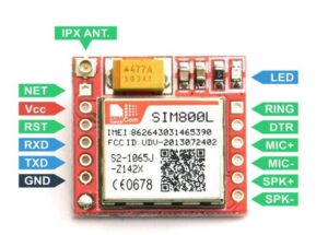
SIM800l Pin Explain
- VCC: is connected to only 3.7V to 4.2V.
- GND: The GND Pin is connected to the 0v.
- TXD: The TXD pin is for transmitting the signal and they will be connected to the RX Pin Of Arduino.
- RXD: The RXD pin is used to receive the signal and it will be connected to the TX Pin of Arduino.
- RST: If anything does not work properly then you just press the RST Button.
- DTR: Data Terminal
- DCD: Data carrier detect
- MIC+: Positive microphone input
- MIC-: Negative microphone input
- SPK+: Positive speaker output
- SPK-: Negative speaker output
- KEY: The Key pin powers on or off the module. It typically requires a high logic level (connected to VCC) for the module to turn on.
- SIM Card Slot: The SIM800L module has an embedded SIM card slot where you can insert a standard-sized SIM card. The SIM card contains subscriber information and is necessary for the module to connect to the GSM network.
- Antenna: The GSM module requires an external antenna for proper reception and transmission of signals. The antenna should be connected to the module’s antenna pin.
Key features of the SIM800L Module
- Communication Interface: The module communicates with UART (Universal Asynchronous Receiver-Transmitter) communication Only.
- SMS and Call Functionality: The SIM800L module can send and receive SMS (Short Message Service) text messages.
- GPRS Data Transfer: GPRS (General Packet Radio Service), allows it to establish a data connection to transmit and receive data packets over the internet. they used TCP/IP (Transmission Control Protocol/Internet Protocol) communication.
- Embedded SIM Card Slot: The SIM800L module features an embedded SIM card slot, which accepts a standard-sized SIM card.
- Power Supply Requirements: They Operate from 3.7V to 4.2V.
- AT Command Set: The SIM800L module communicates using AT Commands. Such as sending SMS, making calls, and establishing data connections.
Application Of SIM800l GSM Module
- IoT (Internet of Things) Projects: IoT projects that require wireless connectivity.
- GPS Tracking Systems: SIM800L module with a GPS module, you can create tracking devices that provide real-time location information.
- Home Automation: Home automation systems enable remote control and monitoring of appliances, security systems, and environmental sensors.
- Remote Monitoring Systems: Remote monitoring systems for applications like weather monitoring, environmental monitoring, and industrial automation.
- Weather Stations: Weather station data can be transmitted to a centralized server for analysis and display.
- Smart Agriculture: They Provide connectivity for monitoring and controlling irrigation systems, greenhouse environments, soil moisture, and weather conditions.
- Vehicle Tracking and Fleet Management: It allows real-time tracking of vehicles and monitoring of driver behaviour.
Interfacing SIM800L GSM Module With Arduino
Connecting The SIM800L To The Network
- Insert SIM Card: Ensure that a valid SIM card is inserted into the SIM card slot on the SIM800L module. The SIM card should have an active GSM subscription and provide network coverage in the area.
- Power Supply: Connect a stable power supply to the VCC and GND pins of the SIM800L module. The module typically operates at a voltage range of 3.7V to 4.2V. Ensure that the power supply can provide sufficient current to meet the module’s requirements, especially during data transmission or voice calls.
- Antenna Connection: Connect an external GSM antenna to the antenna pin of the SIM800L module. The antenna is crucial for proper signal reception and transmission.
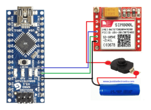
- Serial Communication: Establish serial communication between the SIM800L module and your microcontroller or Arduino board. Connect the TX (Transmit) pin of the SIM800L module to the RX (Receive) pin of the microcontroller and the RX (Receive) pin of the SIM800L module to the TX (Transmit) pin of the microcontroller. Make sure to connect the GND pins of both devices as well.
- Software Setup: Write the necessary code to control the SIM800L module using AT (Attention) commands over the serial interface.
- Network Registration: Before connecting to the network, the SIM800L module needs to register with the GSM network.
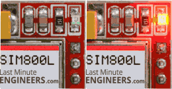
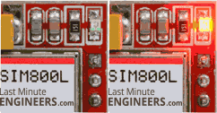
The LED blinking indicates something: Here’s a GIF Image displaying these LED indications.
- Every second: searching for a network.
- Every three seconds: connected to a network.
- Twice per second: connected through GPRS.
CODE
Testing AT Commands With Arduino Code
|
1 2 3 4 5 6 7 8 9 10 11 12 13 14 15 16 17 18 19 20 21 22 23 24 25 26 27 28 29 30 31 32 33 34 35 36 37 38 39 40 41 42 43 44 45 |
#include <SoftwareSerial.h> SoftwareSerial mySerial(2, 3); void setup() { Serial.begin(9600); mySerial.begin(9600); Serial.println("Initializing..."); delay(1000); sendATCommand("AT"); sendATCommand("AT+CMGF=1"); sendATCommand("AT+CNMI=1,2,0,0,0"); } void loop() { updateSerial(); } void sendATCommand(const char* command) { mySerial.println(command); delay(500); while (mySerial.available()) { Serial.write(mySerial.read()); } Serial.println(); } void updateSerial() { delay(500); while (Serial.available()) { mySerial.write(Serial.read()); } while (mySerial.available()) { Serial.write(mySerial.read()); } } |
Sending SMS With Arduino Code
|
1 2 3 4 5 6 7 8 9 10 11 12 13 14 15 16 17 18 19 20 21 22 23 24 25 26 27 28 29 30 31 32 33 34 |
#include <SoftwareSerial.h> SoftwareSerial mySerial(2, 3); void setup() { Serial.begin(9600); mySerial.begin(9600); Serial.println("Initializing..."); delay(1000); sendATCommand("AT"); sendATCommand("AT+CMGF=1"); sendATCommand("AT+CMGS=\"+9188305848xx\""); sendATCommand("Hello i am from JustDoElectronics"); mySerial.write(26); } void loop() { } void sendATCommand(const char* command) { mySerial.println(command); delay(500); while (mySerial.available()) { Serial.write(mySerial.read()); } Serial.println(); }<code> |
Making Call With Arduino Code
|
1 2 3 4 5 6 7 8 9 10 11 12 13 14 15 16 17 18 19 20 21 22 23 24 25 26 27 28 29 30 31 |
#include <SoftwareSerial.h> SoftwareSerial mySerial(2, 3); void setup() { Serial.begin(9600); mySerial.begin(9600); Serial.println("Initializing..."); delay(1000); sendATCommand("AT"); sendATCommand("AT+CMGF=1"); sendATCommand("ATD+9188305848xx;"); } void loop() { } void sendATCommand(const char* command) { mySerial.println(command); delay(500); while (mySerial.available()) { Serial.write(mySerial.read()); } Serial.println(); } |
Conclusion
The SIM800 GSM module provides the capability to send and receive calls and SMS messages using an Arduino or similar microcontroller. By interfacing the SIM800 module with Arduino and utilizing AT commands, you can easily implement call and SMS functionality in your projects.
Sensor

