DC Motor Control Using L298N & Arduino
Introduction
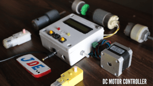
DC motors are widely used in various applications that require precise control of rotation. To control the direction and speed of a DC motor, we can use the L298N motor driver module in combination with an Arduino. In this article, we will explore how to control a DC motor using the L298N module and Arduino, specifically focusing on achieving clockwise and counterclockwise rotation.
Components Required
- Arduino board
- L298N motor driver module
- DC motor
- Power supply (battery or external power source)
- Soldering wires
- Zero PCB
- 4×4 PVC BOX
Arduino Nano
- The Arduino Nano is powered by the ATmega328P microcontroller chip, which is the same microcontroller used in the Arduino Uno board. The ATmega328P operates at a clock speed of 16 MHz and has 32KB of flash memory, 2KB of SRAM, and 1KB of EEPROM.
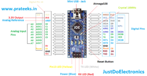
- The Arduino Nano provides a total of 14 digital I/O pins, of which 6 can be used for PWM (Pulse Width Modulation) output. It also offers 8 analog input pins, each of which can provide a 10-bit resolution. These pins allow you to interface with various sensors, actuators, and other electronic components.
L298N Motor Driver
The L298N is a popular and widely used dual H-bridge motor driver integrated circuit (IC). It is commonly used to control the speed and direction of DC motors in robotics, automation, and various other applications. The L298N can handle relatively high currents and voltages, making it suitable for driving medium to large-sized DC motors.
Key Features
- Dual H-Bridge Configuration: The L298N consists of two H-bridge circuits, allowing it to control the direction of two separate DC motors independently. Each H-bridge can drive a motor in either direction (clockwise or counterclockwise) by controlling the polarity and voltage applied to its terminals.
- High Current and Voltage Handling: The L298N can handle a maximum current of 2A per channel (4A total) and can operate within a wide voltage range of 7V to 46V. This capability makes it suitable for driving motors with higher power requirements.
- Built-in Protection: The L298N includes various built-in protection mechanisms to ensure safe and reliable operation. It has integrated flyback diodes that protect the circuit from voltage spikes generated by the motor during switching. Additionally, it features thermal shutdown protection to prevent damage due to excessive heat.
- Enable Pins: The L298N has enabled pins (EN1 and EN2) for each motor channel, which allow you to control the motor’s speed by adjusting the PWM (Pulse Width Modulation) signal. By varying the duty cycle of the PWM signal, you can control the average voltage applied to the motor, thereby controlling its speed.
- Control Inputs: The L298N has four control inputs for each motor channel (IN1, IN2 for motor 1; IN3, IN4 for motor 2). By manipulating the states of these control inputs (HIGH or LOW), you can control the direction of rotation of the motors.
DC Motor
A DC motor, short for a Direct Current motor, is an electrical device that converts direct current electrical energy into mechanical energy. It operates based on the principles of electromagnetism and is widely used in various applications such as robotics, industrial machinery, appliances, and automotive systems.

- Armature: The armature is the rotating part of the motor. It consists of a cylindrical core made of ferromagnetic material with slots to hold the armature windings.
- Commutator: The commutator is a cylindrical device mounted on the armature shaft. It consists of copper segments insulated from each other. The commutator serves as a mechanical rectifier, changing the direction of current flow in the armature windings as the motor rotates.
- Armature Windings: The armature windings are coils of wire wound around the armature core. These windings carry the current that interacts with the magnetic field to produce rotational motion. The windings are typically made of copper wire to ensure good conductivity.
- Permanent Magnets or Field Coils: DC motors can have either permanent magnets or field coils to create the magnetic field. Permanent magnet motors use fixed magnets, while field coil motors use electromagnets. The magnetic field interacts with the current flowing through the armature windings, generating the force necessary for rotation.
Block Diagram
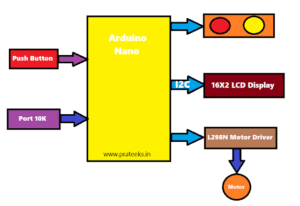
Brief Explanation of Each Component
- Arduino: The Arduino is a microcontroller board that acts as the brain of the system. It receives commands and controls the motor driver and the LCD display.
- L298N Motor Driver: The L298N is a motor driver module that allows you to control the direction and speed of DC motors. It takes input signals from the Arduino and drives the DC motor accordingly.
- 16×2 LCD Display: The 16×2 LCD display is used to provide visual feedback or display relevant information. It connects to the Arduino and allows you to display messages, motor status, or any other information you want to show.
- DC Motor: The DC motor is the motor you want to control. It can be connected to the L298N motor driver, which will control its speed and direction based on the signals received from the Arduino.
The Arduino communicates with the L298N motor driver to control the motor’s speed and direction. It also communicates with the 16×2 LCD display to show relevant information, such as motor status, speed, or any other data you want to display.
To implement this setup, you would need to connect the appropriate pins of the Arduino to the L298N motor driver and the LCD display. The specific connections and code implementation would depend on the pin configurations and libraries you are using.
Circuit Diagram
L298N Motor Driver Connections
- Connect the IN1 and IN2 pins of the L298N motor driver to the digital output pins of the Arduino (e.g., Pin 10 and Pin 11).
- Connect the ENA pin of the L298N motor driver to the PWM-enabled digital output pin of the Arduino (e.g., Pin 9).
- Connect the OUT1 and OUT2 pins of the L298N motor driver to the terminals of the DC motor.
- Connect the GND pin of the L298N motor driver to the GND pin of the Arduino.
I2C Module Connections
- The I2C module acts as an interface between the Arduino and the LCD display. It enables communication using the I2C protocol.
- Connect the SDA (data) pin of the I2C module to the SDA pin on the Arduino.
- Connect the SCL (clock) pin of the I2C module to the SCL pin on the Arduino.
- Connect the VCC pin of the I2C module to the 5V pin on the Arduino.
- Connect the GND pin of the I2C module to the GND pin on the Arduino.
16×2 LCD Connections
- The 16×2 LCD display is connected to the I2C module via its I2C interface.
- The specific pinout and labelling might vary depending on the I2C module and LCD display you are using.
- Typically, the connections include the following:
- VCC: Connect to the VCC pin on the I2C module (5V).
- GND: Connect to the GND pin on the I2C module.
- SDA: Connect to the SDA pin on the I2C module.
- SCL: Connect to the SCL pin on the I2C module.
DC Motor Connections
- Connect one terminal of the DC motor to the OUT1 pin of the L298N motor driver.
Source Code
First We Chek the Motor With the Sample Code
|
1 2 3 4 5 6 7 8 9 10 11 12 13 14 15 16 17 18 19 20 21 22 23 |
const int ENA = 11; // Enable pin for motor 1 const int IN1 = 10; // Control pin 1 for motor 1 const int IN2 = 9; // Control pin 2 for motor 1 void setup() { pinMode(ENA, OUTPUT); pinMode(IN1, OUTPUT); pinMode(IN2, OUTPUT); } void loop() { // Set the speed and direction of the motor analogWrite(ENA, 200); // Set the motor speed (PWM value between 0 and 255) digitalWrite(IN1, HIGH); // Set the motor direction (HIGH or LOW) digitalWrite(IN2, LOW); delay(5000); // Delay for 5 seconds // Stop the motor analogWrite(ENA, 0); // Set the motor speed to 0 (stop) delay(2000); // Delay for 2 seconds } |
Code Explanation
- Define the ENA, IN1, and IN2 pins as constants, representing the enable pin and control pins for motor 1.
- In the
setup()function, set the ENA, IN1, and IN2 pins as OUTPUTs to send control signals to the L298N module. - Inside the
loop()function, the code demonstrates setting the speed and direction of the motor. - Use
analogWrite()on the ENA pin to set the motor speed. The PWM value can range from 0 (minimum speed) to 255 (maximum speed). Adjust this value to control the desired motor speed. - Use
digitalWrite()on the IN1 and IN2 pins to set the motor direction. Setting IN1 to HIGH and IN2 to LOW will make the motor rotate in one direction. Modify these values to change the motor’s rotation direction. - After setting the speed and direction, the code introduces a delay of 5 seconds to allow the motor to run.
- To stop the motor, set the ENA pin’s analog output to 0, effectively turning off the power to the motor.
- Another delay of 2 seconds is added before the code repeats the loop.
Final Code
|
1 2 3 4 5 6 7 8 9 10 11 12 13 14 15 16 17 18 19 20 21 22 23 24 25 26 27 28 29 30 31 32 33 34 35 36 37 38 39 40 41 42 43 44 45 46 47 48 49 50 51 52 53 54 55 56 57 58 59 60 61 62 63 64 65 66 67 68 69 70 71 72 73 74 75 76 77 78 79 80 |
#include <LiquidCrystal_I2C.h> LiquidCrystal_I2C lcd(0x27, 16, 2); #define potentiometer A2 #define bt_F A3 #define bt_S A6 #define bt_B A7 #define M1_Ena 11 #define M1_in1 10 #define M1_in2 9 int read_ADC = 0; int duty_cycle; int duty_cycle_lcd; int set = 0; void setup() { Serial.begin(9600); pinMode(potentiometer, INPUT); pinMode(bt_F, INPUT_PULLUP); pinMode(bt_S, INPUT_PULLUP); pinMode(bt_B, INPUT_PULLUP); pinMode(M1_Ena, OUTPUT); pinMode(M1_in1, OUTPUT); pinMode(M1_in2, OUTPUT); lcd.init(); lcd.backlight(); } void loop() { read_ADC = analogRead(potentiometer); duty_cycle = map(read_ADC, 0, 1023, 0, 255); duty_cycle_lcd = map(read_ADC, 0, 1023, 0, 100); analogWrite(M1_Ena, duty_cycle); lcd.setCursor(0, 0); lcd.print("Duty Cycle: "); lcd.print(duty_cycle_lcd); lcd.print("% "); if (digitalRead(bt_F) == 0) { set = 1; } if (digitalRead(bt_S) == 0) { set = 0; } if (digitalRead(bt_B) == 0) { set = 2; } lcd.setCursor(0, 1); if (set == 0) { lcd.print(" Stop "); digitalWrite(M1_in1, LOW); digitalWrite(M1_in2, LOW); } if (set == 1) { lcd.print(" Clockwise "); digitalWrite(M1_in1, HIGH); digitalWrite(M1_in2, LOW); } if (set == 2) { lcd.print(" Anticlockwise "); digitalWrite(M1_in1, LOW); digitalWrite(M1_in2, HIGH); } delay(50); } |
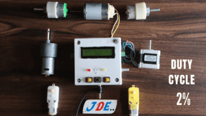
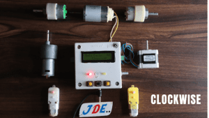
Project Demo
Video Tutorial
If you interested in more Arduino Tutorial
Conclusion
- By combining the L298N motor driver module with an Arduino, you can easily control the direction of a DC motor. The provided code example demonstrates how to rotate the motor clockwise and counterclockwise using the L298N module and Arduino.
- Remember to adjust the pin numbers according to your specific wiring configuration and ensure the compatibility of the power supply and motor specifications. With this knowledge, you can now integrate DC motor control into your projects with ease.
