Understand I2C Communication Protocol
Introduction
In the electronic communication protocols, I2C (Inter-Integrated Circuit) stands out as a widely used and versatile interface for connecting various electronic components within a system. Developed by Philips Semiconductor (now NXP Semiconductors) in the 1980s, I2C has since become a standard communication protocol used in a plethora of applications, ranging from simple sensor interfaces to complex embedded systems. This article aims to provide an overview of the I2C protocol, its key features, and its significance in modern electronics.
What is I2C?
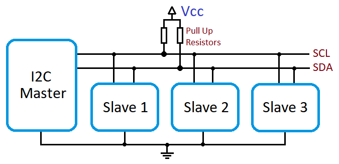
I2C, short for Inter-Integrated Circuit, is a synchronous serial communication protocol that enables digital devices to communicate with each other over short distances. It facilitates the exchange of data between a master device (usually a microcontroller or a processor) and multiple slave devices (such as sensors, memory chips, or peripheral devices) on a shared bus.
Data Frame
Images Taken By Circuit Basics
- Start Condition: The start condition initiates the data frame and indicates the beginning of a new transmission. It is generated by the master device and consists of a high-to-low transition on the SDA (Serial Data Line) while the SCL (Serial Clock Line) is high. The start condition prepares the bus for transmitting the address and data.
- Addressing: After the start condition, the master device transmits the address of the target slave device it wishes to communicate with. The address typically consists of 7 or 10 bits, depending on the addressing mode (7-bit or 10-bit) used in the specific I2C implementation. The address bits are transmitted from the most significant bit (MSB) to the least significant bit (LSB).
- Read/Write Bit: Following the address, the master device sends a single bit known as the Read/Write (R/W) bit. This bit determines the direction of data transfer. When the R/W bit is set to 0, it indicates a write operation (master sending data to the slave). Conversely, when the R/W bit is set to 1, it signifies a read operation (master requesting data from the slave).
- Data Transfer: Once the address and R/W bit have been transmitted, the actual data transfer takes place. Both the master and slave devices can send and receive multiple bytes of data. Each data byte consists of 8 bits transmitted from the MSB to the LSB. After transmitting each byte, the receiver (master or slave) provides an acknowledgement (ACK) to confirm the successful reception of the data. If the ACK is not received, it indicates a transmission error.
- Stop Condition: The stop condition concludes the data frame and signifies the end of the transmission. It is generated by the master device and consists of a low-to-high transition on the SDA line while the SCL line is high. The stop condition releases the bus, allowing other devices to initiate new communications.
Standard Mode
Standard Mode is the original and most commonly used mode in I2C communication. It supports a maximum data transfer rate of 100 kilobits per second (Kbps). In this mode, both the master and slave devices adhere to the timing specifications defined by the I2C standard.
Key Features
- Clock Frequency: The clock frequency in Standard Mode is limited to 100 kHz, meaning the clock signal toggles at a maximum rate of 100,000 times per second.
- Rise and Fall Times: The rise and fall times of the signals on the I2C bus are relatively relaxed in Standard Mode, typically ranging between a few microseconds to tens of microseconds.
- Noise Immunity: Standard Mode provides a reasonable level of noise immunity, ensuring reliable communication in most common operating environments.
- Compatibility: Standard Mode is supported by virtually all I2C-compatible devices, making it the go-to mode for most general-purpose I2C applications.
Fast Mode
Fast Mode is an enhanced version of I2C communication that offers higher data transfer rates compared to Standard Mode. It supports a maximum data transfer rate of 400 kilobits per second (Kbps). Fast Mode is backwards compatible with Standard Mode, allowing devices to communicate with each other regardless of the mode they operate in.
Key Features
- Clock Frequency: In Fast Mode, the clock frequency is increased to a maximum of 400 kHz, enabling faster data transfer between devices.
- Rise and Fall Times: The rise and fall times of the signals on the I2C bus are typically faster in Fast Mode compared to Standard Mode, ranging between a few hundred nanoseconds to a few microseconds.
- Noise Immunity: Fast Mode retains a good level of noise immunity, ensuring reliable communication even at higher data rates.
- Compatibility: Fast Mode is supported by a wide range of I2C devices. However, it is important to note that older or more specialized devices may only support Standard Mode.
Key Features of I2C
- Master-Slave Architecture: I2C utilizes a master-slave architecture, where the master device initiates and controls the communication with the connected slave devices.
- Two-Wire Interface: I2C employs a two-wire interface consisting of a serial data line (SDA) for bidirectional data transfer and a serial clock line (SCL) for synchronizing the data transmission between devices. These lines are shared by all devices on the bus.
- Addressing: Each slave device on the I2C bus has a unique address, allowing the master to selectively communicate with individual devices. The addressing scheme supports up to 128 devices on the bus.
- Multi-Master Support: I2C also provides support for multiple masters on the same bus, allowing for more complex systems where multiple controllers can communicate with the same set of slave devices.
- Synchronous Communication: I2C employs a synchronous communication scheme, where data is transferred in a synchronized manner with the clock signal generated by the master device.
Advantages of I2C
- Simplicity: The I2C protocol is relatively straightforward and easy to implement, requiring minimal hardware overhead.
- Flexibility: With its support for multiple masters and up to 128 slave devices, I2C allows for versatile system designs, accommodating a wide range of applications.
- Wide Adoption: I2C has gained widespread popularity and support from semiconductor manufacturers, ensuring a vast array of compatible devices available in the market.
Disadvantage of I2C
- Limited Distance: One of the drawbacks of the I2C protocol is its limited communication distance. The I2C bus is designed for short-distance communication within a system, typically a few meters. An excessive cable length or interference can degrade signal quality and lead to communication errors. Therefore, for longer distances, additional measures such as signal boosters or other communication protocols may be necessary.
- Slower Speed Compared to Other Protocols: While I2C provides a straightforward and easy-to-use interface, it operates at lower data transfer rates compared to some other communication protocols. The maximum speed in Standard Mode is limited to 100 kilobits per second (Kbps), and in Fast Mode, it reaches a maximum of 400 Kbps. For applications requiring high-speed data transfer, other protocols like SPI (Serial Peripheral Interface) or UART (Universal Asynchronous Receiver-Transmitter) may be more suitable.
Applications
- Sensor Interfaces: Many sensors, such as temperature sensors, humidity sensors, pressure sensors, accelerometers, gyroscopes, and magnetometers, utilize I2C for easy integration with microcontrollers or embedded systems. I2C allows efficient communication between the sensors and the control unit, enabling real-time data acquisition and monitoring.
- Display Interfaces: I2C is commonly used in displays, including OLED (Organic Light-Emitting Diode) and LCD (Liquid Crystal Display) modules. It allows the microcontroller or processor to control and configure the display parameters, such as brightness, contrast, and pixel data, using a simplified interface.
- Memory Modules: I2C is widely employed in memory modules such as EEPROM (Electrically Erasable Programmable Read-Only Memory), FRAM (Ferroelectric Random-Access Memory), and real-time clocks. These modules utilize I2C for easy read-and-write operations, enabling data storage, timekeeping, and system configuration.
- Audio Codecs: I2C is utilized in audio codecs for audio-related applications, including digital-to-analog converters (DACs) and analog-to-digital converters (ADCs). It allows the control of audio settings and parameters, such as volume control, audio routing, and digital signal processing (DSP) configurations.
- Power Management: I2C is utilized in power management ICs (Integrated Circuits) for controlling and monitoring power-related functions in electronic systems. It enables communication between power management ICs, voltage regulators, and other power control devices, facilitating power sequencing, voltage monitoring, and power supply management.
- Embedded Systems: I2C is extensively used in embedded systems for communication between microcontrollers, sensors, and other peripheral devices. It provides a convenient interface for integrating various components in a system, enabling efficient data exchange and control.
More Article
