Temperature + Water Level Indicator With GSM And Arduino
Water Level Indicator With Arduino
Introduction
Efficient water management is crucial in various applications, including agriculture, irrigation, and industrial processes. In this project, we will develop a smart water monitoring system using an Arduino Nano, an ultrasonic sensor, an LM35 temperature sensor, a GSM module, an I2C 16×2 LCD display, and a relay module. The system will provide real-time measurements of water distance and temperature, as well as send alerts via SMS using GSM communication.
- Arduino Nano- The main controller is responsible for data processing and system control.
- GSM Module- Enables the system to send SMS alerts to specified phone numbers in case of critical events or threshold breaches.
- I2C 16×2 LCD Display- Displays real-time water distance and temperature readings.
- Relay Module- Controls external devices, such as pumps or valves, based on certain conditions.
- Ultrasonic Sensor (HC-SR04)- Measures the water distance by calculating the time taken for the ultrasonic pulse to bounce back from the water surface.
- LM35 Temperature Sensor- Provides accurate temperature readings for monitoring the water temperature.
Component Need
- Arduino Nano
- Ultrasonic Sensor (HC-SR04)
- LM35 Temperature Sensor
- GSM Module
- I2C 16×2 LCD Display
- Relay Module
- Wires
- Zero PCB
- Power Supply
Arduino Nano
- The Arduino Nano is powered by the ATmega328P microcontroller chip, which is the same microcontroller used in the Arduino Uno board. The ATmega328P operates at a clock speed of 16 MHz and has 32KB of flash memory, 2KB of SRAM, and 1KB of EEPROM.
- The Nano is significantly smaller compared to other Arduino boards, measuring approximately 45mm x 18mm. It is designed in a compact DIP (Dual Inline Package) format, making it suitable for projects with space constraints or when a smaller form factor is required.
- The Arduino Nano provides a total of 14 digital I/O pins, of which 6 can be used for PWM (Pulse Width Modulation) output. It also offers 8 analog input pins, each of which can provide a 10-bit resolution. These pins allow you to interface with various sensors, actuators, and other electronic components.
Ultrasonic Sensor (HC-SR04)
- The HC-SR04 is an ultrasonic sensor module commonly used in electronics projects to measure distance. It utilizes ultrasound waves to determine the distance between the sensor and an object in its vicinity. The sensor module consists of two primary components: a transmitter and a receiver.
- The transmitter emits high-frequency sound waves (ultrasound) that are inaudible to the human ear. These sound waves travel through the air and bounce off objects in their path. The receiver, positioned alongside the transmitter, picks up the reflected sound waves.
To measure distance, the HC-SR04 utilizes the time it takes for the sound waves to travel from the transmitter, hit an object, and return to the receiver. The module has four pins: VCC (power supply), Trig (trigger), Echo (echo signal), and GND (ground).
HC-SR04 Working
- Trigger Signal: To initiate the distance measurement, a short 10-microsecond pulse is sent to the Trig pin of the module. This triggers the transmitter to emit an ultrasonic pulse.
- Sound Wave Emission: The transmitter converts electrical energy into sound energy, producing a burst of ultrasonic sound waves that spread out in a cone-shaped pattern from the sensor.
- Object Reflection: When sound waves encounter an object, they bounce back or reflect off its surface. The time it takes for the waves to travel to the object and return depends on the distance.
- Echo Signal: The reflected sound waves are picked up by the receiver. They cause the Echo pin of the module to go high, indicating that the waves have been received.
- Time Measurement: The microcontroller or the circuit connected to the HC-SR04 starts measuring the time it takes for the Echo pin to go from low to high. This duration is proportional to the distance between the sensor and the object.
- Distance Calculation: Using the measured time and the speed of sound, the distance can be calculated. The speed of sound is approximately 343 meters per second (or 0.0343 centimetres per microsecond) at room temperature.
LM35 Temperature Sensor
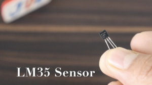
The LM35 is a temperature sensor that is widely used in electronics projects to measure ambient temperature accurately. It is an analog sensor that provides an output voltage proportional to the temperature being sensed. The LM35 sensor is popular due to its simplicity, low cost, and wide temperature measurement range.
LM35 Sensor Works
- Voltage Output: The LM35 sensor operates on the principle of the linear voltage temperature coefficient of its output voltage. It generates an output voltage that is linearly proportional to the temperature it senses.
- Temperature Sensing: The LM35 sensor can measure temperatures in the range of -55°C to +150°C. The sensor is designed to have a linear voltage-output relationship, where the output voltage increases by 10 millivolts per degree Celsius rise in temperature.
- Pin Configuration: The LM35 sensor has three pins: VCC (power supply), GND (ground), and OUT (analog output). VCC and GND pins are connected to the power supply and ground, respectively. The OUT pin is where the analog output voltage is obtained.
- Power Supply: The LM35 sensor operates on a power supply voltage typically ranging from 4V to 30V. It is capable of operating over a wide voltage range, which adds to its versatility.
- Output Voltage Calculation: The LM35 sensor’s output voltage is directly proportional to the sensed temperature. The output voltage can be calculated using the formula: Output Voltage (in millivolts) = Temperature (in °C) × 10
For example, if the sensor measures a temperature of 25°C, the output voltage would be 250 mV.
-
- Analog-to-Digital Conversion: To interface the LM35 sensor with digital systems, such as microcontrollers or Arduino boards, the analog output voltage needs to be converted into a digital value. This conversion is achieved using an analog-to-digital converter (ADC) present in the microcontroller or by using external ADC modules.
- Calibration: The LM35 sensor may require calibration to ensure accurate temperature measurements. Calibration involves comparing the sensor’s output voltage at known temperatures and adjusting the readings accordingly.
GSM Module
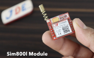
GSM SIM800L is a popular module that enables communication over GSM (Global System for Mobile Communications) networks. It provides functionalities for making calls, sending and receiving SMS messages, and connecting to the internet.
- The GSM SIM800L module is designed to work with GSM networks, allowing devices to establish communication through cellular networks. It operates on various frequencies and supports 2G,3G connectivity, making it compatible with most GSM networks worldwide.
- The module requires a power supply of around 3.7 to 4.2 volts. It can be powered using an external power source, such as a battery or a regulated power supply. It is important to ensure a stable power supply to ensure reliable operation.
- The module communicates with other devices, such as microcontrollers or computers, using serial communication. It typically utilizes UART (Universal Asynchronous Receiver-Transmitter) protocol, enabling devices to send and receive commands and data through serial communication.
I2C 16×2 LCD Display
A 16×2 LCD display refers to a liquid crystal display with two rows and 16 characters per row. It is a commonly used alphanumeric display in many electronic projects and devices. The I2C (Inter-Integrated Circuit) interface is a communication protocol that allows for easy and efficient communication between microcontrollers and peripheral devices.
- When an LCD display is connected using the I2C interface, it typically requires fewer pins compared to a direct parallel connection, making it more convenient for projects with limited available pins on the microcontroller.
- I2C Interface: The I2C interface uses a master-slave communication protocol. The microcontroller acts as the master and the LCD display module as the slave. The I2C interface allows for multiple devices to be connected on the same bus, each with a unique address.
- I2C Address: The LCD display module with an I2C interface has a specific address that is set by the manufacturer. This address can usually be found in the documentation or can be identified using an I2C scanner program.
Relay Module
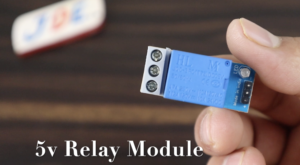
A relay module is an integrated circuit board that incorporates a relay and additional components for easy integration into electronic projects. It provides a convenient way to control higher voltage or current loads using a lower voltage signal, such as the output from a microcontroller or Arduino.
The relay itself is the primary component of the module. It consists of an electromagnet and a set of contacts. The contacts can be normally open (NO), normally closed (NC), or both, depending on the relay type. When the coil of the relay is energized, the contacts change their state.
Circuit Diagram
Arduino Nano
- Connect the 5V pin to the VCC pins of the GSM module, I2C LCD display, ultrasonic sensor, LM35 temperature sensor, and relay module.
- Connect the GND pin to the GND pins of the GSM module, I2C LCD display, ultrasonic sensor, LM35 temperature sensor, and relay module.
GSM Module
- Connect the TX pin of the GSM module to a digital input pin (e.g., Pin 10) of the Arduino Nano.
- Connect the RX pin of the GSM module to a digital output pin (e.g., Pin 11) of the Arduino Nano.
- I2C 16×2 LCD Display
- Connect the SDA pin of the I2C LCD display to the SDA pin (A4) of the Arduino Nano.
- Connect the SCL pin of the I2C LCD display to the SCL pin (A5) of the Arduino Nano.
Relay Module
- Connect the control pin (IN1) of the relay module to a digital output pin (e.g., Pin 7) of the Arduino Nano.
- Connect the VCC pin of the relay module to the 5V pin of the Arduino Nano.
- Connect the GND pin of the relay module to the GND pin of the Arduino Nano.
Ultrasonic Sensor
- Connect the VCC pin of the ultrasonic sensor to the 5V pin of the Arduino Nano.
- Connect the GND pin of the ultrasonic sensor to the GND pin of the Arduino Nano.
- Connect the Trig pin of the ultrasonic sensor to a digital output pin (e.g., Pin 5) of the Arduino Nano.
- Connect the Echo pin of the ultrasonic sensor to a digital input pin (e.g., Pin 6) of the Arduino Nano.
LM35 Temperature Sensor
- Connect the VCC pin of the LM35 temperature sensor to the 5V pin of the Arduino Nano.
- Connect the GND pin of the LM35 temperature sensor to the GND pin of the Arduino Nano.
- Connect the output pin (middle pin) of the LM35 temperature sensor to an analog input pin (e.g., A0) of the Arduino Nano.
Power Supply
-
- Connect the positive terminal of the power supply to the VCC pins of the components.
- Connect the negative terminal of
PCB Design
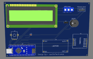
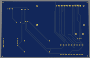
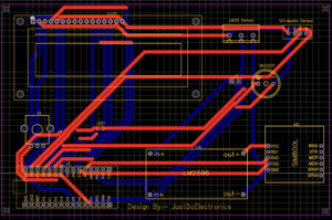
- Here we used the EasyEDA Software to design the project’s PCB
EasyEDA is a web-based electronic design automation (EDA) software that allows users to design, simulate, and prototype electronic circuits and printed circuit boards (PCBs). It provides a user-friendly interface and a set of powerful tools to assist in the entire process of electronic design.
Source Code
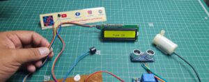
Project Demo
Water Level Measurement
-
- The ultrasonic sensor detects the water surface by sending ultrasonic pulses and measuring the time it takes for the echoes to return.
- The Arduino Nano calculates the distance between the sensor and the water surface using the measured time.
- Real-time water distance readings are displayed on the LCD display.
- If the water level falls below or exceeds predefined thresholds, the system can trigger an alert or control external devices using the relay module.
Temperature Measurement
-
- The LM35 temperature sensor measures the water temperature.
- The Arduino Nano reads the sensor values and displays the temperature reading on the LCD display.
- Thresholds can be set to trigger alerts if the water temperature reaches critical levels, indicating potential issues or unsuitable conditions.
LCD Display Integration
-
- Connect the 16×2 LCD display module to the Arduino board.
- Utilize the LiquidCrystal library and appropriate Arduino pins to control the LCD display.
- Write Arduino code to initialize the LCD display and display the water level and temperature readings.
- Use the LCD display functions to show the measured values in the desired format.
GSM Alert System
- In the event of critical water level or temperature conditions, the Arduino Nano communicates with the GSM module to send SMS alerts to designated phone numbers.
- The SMS includes relevant information, such as the type of alert (water level or temperature) and the current readings.
Prototyping and Testing
-
- Assemble the components and connect them as per the circuit design.
- Upload the Arduino code to the board.
- Test the system by immersing the water level sensor in different water levels and verifying the accuracy of the measurements.
- Verify the temperature readings against a known temperature source to ensure accuracy.
- Test the LCD display functionality by checking if the water level and temperature values are correctly displayed.
- Test the GSM functionality by sending SMS or making calls to the designated recipient with the measured data.
Video Tutorial
Conclusion
By combining an ultrasonic sensor, LM35 temperature sensor, GSM module, I2C 16×2 LCD display, relay module, and Arduino Nano, we have developed a smart water monitoring system. This system offers real-time monitoring of water distance and temperature, enabling proactive management and timely interventions. It can be applied in various water-related applications, promoting efficient resource utilization and preventing potential issues.
Arduino Based Projects


