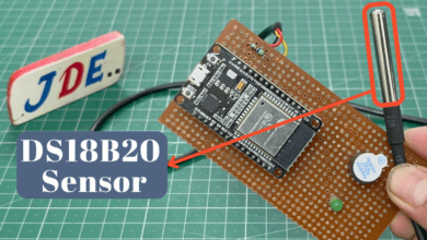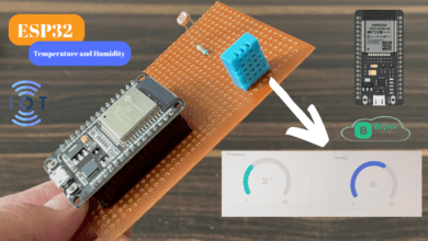
IoT Based Temperature Monitoring System Using ESP32 With Blynk App
Temperature Monitoring System Using ESP32 With Blynk App
Introduction
The Internet of Things (IoT) has revolutionized various industries, enabling the development of smart and interconnected systems. In this project, an IoT-based temperature monitoring system using the ESP32 microcontroller and Blynk app was implemented.
The system utilizes DTH11 and DS18B20 sensors to measure temperature and a 16×2 LCD display to display the temperature readings. The Blynk app provides remote monitoring and control of the system. This project demonstrates the integration of hardware, software, and cloud-based applications to create an efficient temperature monitoring solution.
In this article, we will create an Internet of Things-based temperature monitoring system using the ESP32 development board and the Blynk app. This project will allow you to remotely monitor temperature readings in real time.
- How To Intall ESP32 Board In Arduino IDE Click Here
Components Needed
S.N | Component | Quantity | Link To Buy |
1 | ESP32 Board | 1 | |
2 | DHT11 Sensor | 1 | |
3 | DS18B20 sensor | 1 | |
4 | 4.7Kohm Resister | 1 | |
5 | 16x2 LCD Display With I2C | 1 | |
6 | Zero PCB | 1 |
ESP32 Board
- ESP32 is a popular microcontroller board that is based on the ESP32 system-on-chip (SoC) developed by Espressif Systems.
- The ESP32 board includes a dual-core processor, built-in Wi-Fi and Bluetooth connectivity, making it suitable for a wide range of projects.
- Microcontroller- 32-bit Xtensa LX6 dual-core processor, which operates at a clock speed of up to 240 MHz. The dual-core architecture allows for multitasking tasks.
Features
- Memory: 520Kb SRAM
- WiFi: 802.11/g/n/e/i
- Bluetooth: v4.2 BR/EDR And BLE
- CPU: Xtensa Dual-core(or Single-core) 32-bit LX6 Microprocessor, Operating at 160 or 240 MHz And Performing at up to 600 DMIPS
- 10 × touch sensors
- Hall sensor
- LED PWM up to 16 channels
- Ultra-low Power (ULP) Co-Processor
- 12-Bit SAR ADC up to 18 channels
- 2×8-bit DAC’s
- 4x SPI
- 2xI2S Interfaces
- 2xI2C Interfaces
- 3xUART
- Low Power Mode
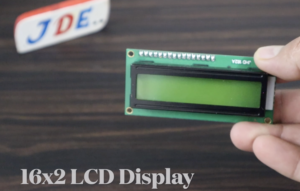
16×2 LCD Display
16×2 LCD display with I2C refers to a liquid crystal display (LCD) module that consists of 16 columns and 2 rows of characters.
- I2C Interface- The I2C interface on the LCD display module allows you to control the display using I2C commands.
- I2C Module- PCF8574 or PCF8574A acts as an I/O expander.
- Wiring-
- VCC and GND: Connect 5v power supply and GND to GND pins of the LCD display and the microcontroller.
- SDA (Serial Data) and SCL (Serial Clock): I2C PIN like if used then connected the A5 and A4.
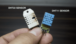
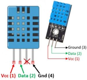
DHT11 Sensor
DHT11 sensor is a widely used digital temperature and humidity sensor in various projects. The sensor is small in size and can be easily integrated into any Microcontroller.
Sensing Elements
The DHT11 sensor contains a humidity-sensing component and a temperature-sensing component.
Humidity Sensing
- The humidity-sensing component consists of a moisture-sensitive capacitor. It absorbs moisture from the surrounding environment, causing changes in its capacitance.
Temperature Sensing
- The temperature-sensing component uses a thermistor, which is a type of resistor whose resistance changes with temperature. By measuring the resistance, the sensor determines the temperature.
Analog-to-Digital Conversion
- The DHT11 sensor internally performs analogue-to-digital conversion to convert the measured analog signals (humidity and temperature) into digital values that can be read by a microcontroller.
DS18B20 sensor
- DS18B20 is a popular digital temperature sensor widely used in various projects and applications.
- The DS18B20 uses the 1-Wire protocol, which enables communication and power supply over a single data line.
Digital Thermometer
- The DS18B20 is a digital thermometer specifically designed to measure temperature. It eliminates the need for analogue-to-digital conversion by providing temperature readings directly in a digital format.
One-Wire Protocol
- The DS18B20 sensor uses the 1-Wire protocol, which allows multiple sensors connected to a single data line. This connects multiple sensors to a single microcontroller pin, using a unique address for each sensor.
Circuit Diagram
Here is an explanation of the circuit diagram for the IoT-based temperature monitoring system using ESP32, DTH11, DS18B20 sensors, and a 16×2 LCD display.
- 16×2 LCD is conected to the I2C protocol is conected to SDA Pin to D21 And SCL Pin conected to the D22 Pin in ESP32 Board.VCC Coneted to the 5v And GND will Conected to the GND.
- DHT11 Sensir Is conected to the pin Number D18 and VCC to 5v,GND to GND.
- DS18B20 sensors is conected to the pin number D19 and VCC to 5v,GND to GND.
Blynk App Setup
- Download the Blynk app from the Google Play Store or Apple App Store.
- Create a new project in the Blynk app and obtain the authentication token.
- Add widgets in the app, such as a value display for temperature readings.
Source Code
Blynk Library — Download
Upload Code To ESP32 Board
- Connect the ESP32 board to the computer using a USB cable.
- Select the appropriate board and port in the Arduino IDE.
- Upload the Arduino code to the ESP32 board.
|
1 2 3 4 5 6 7 8 9 10 11 12 13 14 15 16 17 18 19 20 21 22 23 24 25 26 27 28 29 30 31 32 33 34 35 36 37 38 39 40 41 42 43 44 45 46 47 48 49 50 51 52 53 54 55 56 57 58 59 60 61 62 63 64 65 66 67 68 69 70 71 72 73 74 75 76 77 78 79 80 |
#include <WiFi.h> #include <LiquidCrystal_I2C.h> #include <DHT.h> #include <OneWire.h> #include <DallasTemperature.h> #include <BlynkSimpleEsp32.h> char auth[] = "YOUR_AUTH_TOKEN"; char ssid[] = "YOUR_WIFI_SSID"; char pass[] = "YOUR_WIFI_PASSWORD"; LiquidCrystal_I2C lcd(0x27, 16, 2); // DTH11 Sensor #define DHTPIN 18 #define DHTTYPE DHT11 DHT dht(DHTPIN, DHTTYPE); // DS18B20 Sensor #define ONE_WIRE_BUS 19 OneWire oneWire(ONE_WIRE_BUS); DallasTemperature sensors(&oneWire); #define VIRTUAL_PIN_TEMP BLYNK_VIRTUAL_PIN_START #define VIRTUAL_PIN_HUMIDITY BLYNK_VIRTUAL_PIN_START + 1 void setup() { Serial.begin(115200); lcd.begin(16, 2); lcd.setBacklight(LOW); dht.begin(); sensors.begin(); WiFi.begin(ssid, pass); while (WiFi.status() != WL_CONNECTED) { delay(1000); Serial.println("Connecting to WiFi..."); } Serial.println("Connected to WiFi"); Blynk.begin(auth, ssid, pass); } void loop() { Blynk.run(); float temperature = readDTH11Temperature(); float humidity = readDTH11Humidity(); float dsTemperature = readDS18B20Temperature(); lcd.clear(); lcd.setCursor(0, 0); lcd.print("Temp: "); lcd.print(temperature); lcd.print(" C"); lcd.setCursor(0, 1); lcd.print("Humidity: "); lcd.print(humidity); lcd.print("%"); Blynk.virtualWrite(VIRTUAL_PIN_TEMP, temperature); Blynk.virtualWrite(VIRTUAL_PIN_HUMIDITY, humidity); delay(1000); } float readDTH11Temperature() { float temperature = dht.readTemperature(); return temperature; } float readDTH11Humidity() { float humidity = dht.readHumidity(); return humidity; } float readDS18B20Temperature() { sensors.requestTemperatures(); float temperature = sensors.getTempCByIndex(0); return temperature; } |
Video
Conclusion
The IoT-based temperature monitoring system using ESP32, DTH11, DS18B20 sensors, and a 16×2 LCD display with the Blynk app provides an efficient and convenient solution for remote temperature monitoring. The system demonstrates the integration of IoT devices and cloud-based applications to enable real-time data monitoring and visualization. This project highlights the practical application of IoT technology in home automation and monitoring systems.
ESP32 Related More Projects

