GPS Tracker Using Arduino
Realtime GPS Tracker Using Arduino with sim800l GSM Module
Introduction
In this article, I design a simple GPS tracking System using the Arduino Nano, GSM(Sim800l) and GPS(NEO-6m). GPS tracker is essential because you are used in various fields like Bike, Car and product tracking Systems.
Most GPS tracking system is available in the market but is too costly.so, I decided to design my own small GPS tracking system. The system will send you the location of your mobile phone along with Google Maps. You can request the location at any time and with just one click you check out the proper location.
This is a cheaper solution and is a two-way GPS Communication system where the communication is done in both ways with the help of GPS satellites.
Bill Of Material
Here I used a few components first I prefer the combat size, low power consumption and faster response. that is why I used the component.
S.N | Component's | Quantity |
1 | Arduino Nano | 1 |
2 | GPS Neo6m Module | 1 |
3 | GSM Sim800l Module | 1 |
4 | 5v 1Channel Realy Module | 1 |
5 | 3.7v Lithium ion Battery | 1 |
6 | Zero PCB | 1 |
7 | LED | 1 |
GPS Module
BN-220 GPS Module
The Beitian BN-220 is a dual GPS and GLONASS (Global Navigation Satellite System) module. This means it can receive signals from both GPS and GLONASS satellites, which can improve the accuracy and reliability of positioning data.
To use the Beitian BN-220, you’ll need to connect it to a microcontroller using UART communication. You’ll also need to power it, typically with 3.3V or 5V.
- GND, Black Wire
- TX, White Wire
- RX, Green Wire
- VCC, Red Wire (2.8V-6.0V)
But Beitian BN-220 is a Costly GPS Module
if you used the NEO-6m Module
GPS module that is based on the NEO-6M. This Module uses the latest technology to give the best possible positioning information.
Here I just show the proper image of the GPS Module As you check the image is a small antenna connected to the GPS Module and is a small LED light Indicator for the signal.
and is connected to the UART Protocol Through just used the Tx and Rx Pin and you can use any microcontroller and its operating voltage is 3.3v to 5v.
Features
- Operating temperature range:- -40 TO 85°C
- Supply voltage:- 3.3v to 5v
- The cold start time of:- 38 s
- Baud rates:- 9600
Circuit Diagram
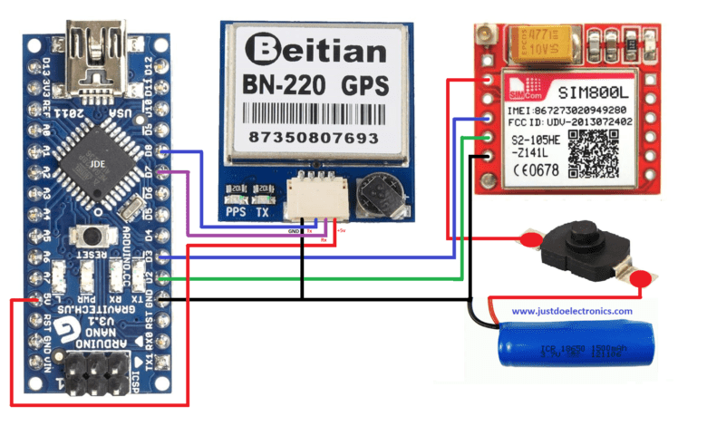
I will design the proper circuit diagram so you do all connections correctly and put the SIM card in the GSM Module.
- GPS Module Is connected to the PIN D7 And D8.
- The GSM Module Is connected to the PIN D2 And D3.
- The relay Module is connected to the D4 and All GND Will be Connected to the common.
We Used The 3.7-volt Lithium-ion battery to give the proper power source to the GSM Module.
Circuit Diagram With Neo-6m GPS Module
Code
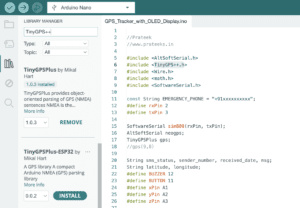
Important library
Before you upload the code in Arduino Nano fist you first change a few things then you upload the code
|
1 |
GSM.println("AT+CMGS=\"+91xxxxxxxxx\""); |
Here you type your country code and mobile number correctly
|
1 2 3 4 5 6 7 8 9 10 11 12 13 14 15 16 17 18 19 20 21 22 23 24 25 26 27 28 29 30 31 32 33 34 35 36 37 38 39 40 41 42 43 44 45 46 47 48 49 50 51 52 53 54 55 56 57 58 59 60 61 62 63 64 65 66 67 68 69 70 71 72 73 74 75 76 77 78 79 80 81 82 83 84 85 86 87 88 89 90 |
#include <TinyGPS++.h> #include <SoftwareSerial.h> SoftwareSerial GSM(2, 3); SoftwareSerial neo(7, 8); String textMessage; String lampState; String lati = ""; String longi = ""; int led = 13; const int relay = 12; TinyGPSPlus gps; void setup() { pinMode(led, OUTPUT); pinMode(relay, OUTPUT); digitalWrite(relay, HIGH); Serial.begin(9600); GSM.begin(9600); neo.begin(9600); GSM.listen(); delay(5000); digitalWrite(led, HIGH); Serial.print("GSM ready...\r\n"); GSM.print("AT+CMGF=1\r\n"); delay(1000); GSM.print("AT+CNMI=2,2,0,0,0\r\n"); delay(1000); digitalWrite(led, LOW); } void loop() { delay(2); while (GSM.available() > 0) { digitalWrite(led, HIGH); textMessage = GSM.readString(); Serial.print(textMessage); delay(10); digitalWrite(led, LOW); } neo.listen(); if (textMessage.indexOf("ON") >= 0) { digitalWrite(relay, LOW); lampState = "ON"; Serial.println("Bike set to ON\r\n"); textMessage = ""; GSM.println("AT+CMGS=\"+9188305848xx\""); delay(500); GSM.print("Bike set to ON\r"); GSM.write(0x1a); delay(1000); GSM.println("AT+CMGD=1,4"); } if (textMessage.indexOf("OFF") >= 0) { digitalWrite(relay, HIGH); lampState = "OFF"; Serial.println("Bike set to OFF\r\n"); textMessage = ""; GSM.println("AT+CMGS=\"+9188305848xx\""); delay(500); GSM.print("Bike set to OFF\r"); GSM.write(0x1a); delay(1000); GSM.println("AT+CMGD=1,4"); } if (textMessage.indexOf("GETLOC") >= 0) { smartDelay(1000); Serial.println("GPS data Recived\r\n"); textMessage = ""; GSM.println("AT+CMGS=\"+9188305848xx\""); delay(500); String pesan = "https://maps.google.com/?q=" + lati + "," + longi; GSM.print(pesan); GSM.write(0x1a); delay(1000); GSM.println("AT+CMGD=1,4"); } } static void smartDelay(unsigned long ms) { unsigned long start = millis(); do { delay(2); while (neo.available()) gps.encode(neo.read()); } while (millis() - start < ms); lati = String(gps.location.lat(), 8); longi = String(gps.location.lng(), 6); Serial.println(lati); Serial.println(longi); } |
Working
First, you give the proper supply turn on the system wait for the signal if both LEDs work perfectly I mean GSM And GPS LED, both modules get the proper signal then you just type the “GETLOC” message and send it to the number when you used in the GSM module.
If GSM receives the message wait for a few min then GSM sends the feedback message with the proper GPS Location (Latitude and Longitude).
You turn on and off the bike or car with the help of the message, just type the “ON” message and send it to the GSM received the message and relay will ON, Same as the off condition just type the “OFF” message and send it GSM module receives the message and relay will OFF.
Video
Conclusion
My Experience is that the project works not badly but is required for the improvement of the future I will try to design more perfectly.
If the GPS tracker project does not work then make sure is not the GPS module in signal range just wait for the signal and then use it and also check the GSM Module.
We Have Also built many types of GPS Tracker


