Understand SPI Communication Protocol
Introduction
The Serial Peripheral Interface (SPI) is a widely adopted synchronous communication protocol that enables the exchange of data between devices over short distances. It is commonly used in various applications, including microcontrollers, sensors, and peripheral devices. In this article, we will delve into the fundamental principles and characteristics of the SPI protocol.
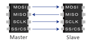
- MOSI (Master Output/Slave Input) – The master sends data to the slave.
- MISO (Master Input/Slave Output) – The slave sends data to the master.
- SCLK (Clock) –The clock signal.
- SS/CS (Slave Select/Chip Select) – Master to select which slave to send data.
SPI relies on four essential communication lines
Serial Clock (SCLK), Master Out Slave In (MOSI), Master In Slave Out (MISO), and Slave Select/Chip Select (SS/CS). The SCLK line is responsible for generating clock pulses that synchronize data transmission. The MOSI line enables the master device to send data to the slave(s), while the MISO line allows the slave(s) to send data back to the master. The SS/CS line is utilized by the master to select the specific slave device it wishes to communicate with.
Data Transfer Process
SPI operates in full-duplex mode, meaning data can be transmitted simultaneously in both directions. The master device initiates the data transfer by generating clock pulses on the SCLK line. Each clock pulse triggers the exchange of one bit of data between the master and the slave(s). The master shifts data out via the MOSI line, while data is received from the slave(s) through the MISO line.
Clock Polarity and Phase
SPI offers flexibility through its configuration of clock polarity (CPOL) and clock phase (CPHA). CPOL determines the idle state of the clock line (high or low), while CPHA determines when the data is captured or changed relative to the clock signal. By adjusting CPOL and CPHA, different data formats (modes 0, 1, 2, or 3) can be achieved, allowing for compatibility with various devices.
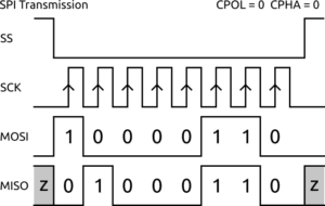
Mode 0
-
- CPOL = 0 (clock idle state is low)
- CPHA = 0 (data is captured on the leading edge of the clock, and data changes on the trailing edge)
- In mode 0, the clock line is idle low, and data is captured by the slave device on the rising edge (transition from low to high) of the clock. Data changes are made by the master device on the falling edge (transition from high to low) of the clock.
Mode 1
-
- CPOL = 0 (clock idle state is low)
- CPHA = 1 (data is changed on the leading edge of the clock, and data is captured on the trailing edge)
- In mode 1, the clock line is idle low, and data changes occur on the rising edge of the clock. The slave device captures the data on the falling edge of the clock.
Mode 2
-
- CPOL = 1 (clock idle state is high)
- CPHA = 0 (data is captured on the leading edge of the clock, and data changes on the trailing edge)
- In mode 2, the clock line is idle high, and data is captured by the slave device on the falling edge of the clock. Data changes are made by the master device on the rising edge of the clock.
Mode 3
-
- CPOL = 1 (clock idle state is high)
- CPHA = 1 (data is changed on the leading edge of the clock, and data is captured on the trailing edge)
- In mode 3, the clock line is idle high, and data changes occur on the rising edge of the clock. The slave device captures the data on the falling edge of the clock.
It’s important to note that the mode selection must be consistent between the master and slave devices. The choice of mode depends on the specific requirements of the devices involved in the SPI communication.
Master-Slave Relationship
The master device assumes control over the communication process by asserting the SS/CS line to select a specific slave. Multiple slaves can be communicated with by employing separate SS/CS lines for each slave or by utilizing daisy-chaining techniques.
Data Frame Format
SPI does not impose a fixed frame format. The data can be transmitted in chunks of 8, 16, or even more bits, depending on the devices involved. Consensus between the master and slave(s) is necessary regarding the data frame size and the order in which bits are transmitted.
Speed and Timing
The speed of data transfer in SPI is determined by the clock frequency (SCLK), which can be configured within the supported range of the devices involved. Timing requirements, including clock frequency, setup time, and hold time, are specified in the datasheets provided by device manufacturers.
Advantage Of SPI
- Simplicity: SPI is relatively simple to implement and understand compared to other communication protocols. It uses a straightforward master-slave architecture with a few communication lines, making it easier to design and integrate into electronic systems.
- High-Speed Data Transfer: SPI supports high-speed data transfer, making it suitable for applications that require quick and efficient communication. The clock frequency (SCLK) can be adjusted within the supported range of the devices, allowing for faster transmission rates.
- Full-Duplex Communication: SPI operates in full-duplex mode, enabling simultaneous data transmission in both directions. This feature allows for efficient and real-time exchange of data between the master and slave devices.
- Flexibility: SPI provides flexibility in terms of clock polarity (CPOL) and clock phase (CPHA) configurations. These settings can be adjusted to meet the timing requirements of different devices. SPI supports multiple modes (mode 0, 1, 2, and 3) that allow developers to choose the most suitable timing relationship between the clock signal and the data.
- Wide Device Support: SPI is widely supported across various microcontrollers, sensors, and peripheral devices. It has become a de facto standard in many industries, ensuring compatibility between devices from different manufacturers.
- Support for Multiple Slaves: SPI supports communication with multiple slave devices. Each slave is assigned a dedicated Slave Select/Chip Select (SS/CS) line, allowing the master to select and communicate with individual slaves as needed. This feature facilitates communication with multiple devices in a system without requiring additional complex addressing schemes.
- Short-Distance Communication: SPI is well-suited for communication over short distances, typically within a system or on a circuit board. It is commonly used for communication between components that are physically close to each other, such as microcontrollers and peripheral devices.
Disadvantage Of SPI
- Higher Pin Count: SPI requires a separate communication line (MOSI, MISO, SCLK, and SS/CS) for each device connected to the bus. This can result in a higher pin-count requirement compared to other serial communication protocols like I2C, which can limit its use in devices with a limited number of available pins.
- Point-to-Point Communication: SPI operates in a point-to-point configuration between the master and each individual slave device. This means that simultaneous communication between multiple slave devices is not possible without additional measures like daisy-chaining or using separate SS/CS lines for each slave. This limitation can increase the complexity of the system design when working with multiple slaves.
- Limited Distance: SPI is primarily designed for communication over short distances, typically within a system or on a circuit board. It does not have built-in mechanisms to handle noise or signal degradation over long distances. If long-distance communication is required, additional measures such as signal conditioning or the use of other communication protocols like RS-485 or Ethernet may be necessary.
- Higher Power Consumption: SPI generally requires more power to operate compared to other serial communication protocols. This is mainly due to the need for separate SS/CS lines for each slave device and the higher pin count requirement.
Application
- Display Modules: SPI is used in various display modules, such as LCDs (Liquid Crystal Displays) and OLEDs (Organic Light-Emitting Diodes), to transfer data and commands from a microcontroller or graphics controller to drive the display pixels. SPI’s high-speed capabilities make it suitable for updating display content in real-time.
- Memory Devices: SPI flash memory and EEPROM (Electrically Erasable Programmable Read-Only Memory) devices use SPI for reading and writing data. These devices are commonly found in embedded systems where non-volatile storage is required, such as in data loggers, industrial control systems, and consumer electronics.
- Communication Modules: SPI is utilized in various communication modules, such as Ethernet controllers, Wi-Fi modules, and radio transceivers, for interfacing with microcontrollers or host systems. It enables data exchange and control between the module and the main system, facilitating wireless communication capabilities.
- Automotive Applications: SPI is used in automotive systems for communication between microcontrollers and components such as sensors, actuators, display panels, and driver assistance systems. It allows for real-time data transfer, supporting critical functions in the vehicle.
- Industrial Automation: SPI is employed in industrial automation systems for communication between control units and peripheral devices like sensors, actuators, and human-machine interfaces (HMIs). It enables fast and reliable data transfer, facilitating real-time control and monitoring.
Conclusion
In summary, the Serial Peripheral Interface (SPI) protocol is a widely used synchronous communication standard that facilitates data exchange between devices over short distances. With its simple design, flexibility in clock polarity and phase configurations, and high-speed capabilities, SPI has become an integral part of various electronic systems. By understanding the key elements and principles of SPI, developers can effectively utilize this protocol in their designs, enabling seamless communication between devices.
More Article
