Introduction
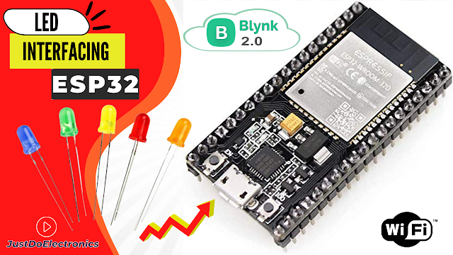
In this Project, We Will Build A Small Home Automation System using ESP32 And the Blynk App. we will use the Arduino IDE Software for programming. we control the home applications wirelessly.
Also, we show how to control the LED over the internet using the Blynk application. so we make this tutorial the basis for the projects I will create more projects in future.
Just flow the Blog and Install ESP32 Driver in Arduino Ide
this tutorial is very used in future projects. just flow the blog and do step by step.
Bill Of Materials
S.N | Component | Quantity | Link To Buy |
1 | ESP32 Module | 1 | |
2 | LED | 4 | |
3 | Bradboard | 1 |
ESP32 Board
In this Project, we Used The ESP32 Board so many GPIO Pins are Available to connect to multiple Systems.
Features
- Includes Chip is CP2102 USB-UART Bridge
- IS operating Power Supply is 5v
- IS also Supported three Modes Ap, STA and AP+STA
- IS Also Supports the RTOS
LED’s
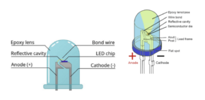
LED (Light-Emitting Diode)
- is 2 pin Anode(+) and Cathode(-)
- is operating voltage is 1.5v to 3v
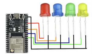
Circuit Diagram
We just connected the led to ESP32 Pin Number Is 33,26,14 And 13
Source Code
Blynk Library — Download
Before You upload the Code You Just Change The Auth token and Wifi Credentials
|
1 2 3 |
#define BLYNK_TEMPLATE_ID "TMPLjOi0Rz-W" #define BLYNK_DEVICE_NAME "esp32" #define BLYNK_AUTH_TOKEN "UF3ok0_l0VkhTDS-WD1gWZ65DdhnHpwx" |
|
1 2 |
char ssid[] = "prateek"; char pass[] = "@@12345"; |
|
1 2 3 4 5 6 7 8 9 10 11 12 13 14 15 16 17 18 19 20 21 22 23 24 25 26 27 28 29 30 31 32 33 34 35 36 37 38 39 40 41 42 43 44 45 46 47 48 49 50 51 52 53 54 55 56 57 58 59 60 61 62 63 64 65 66 67 68 69 70 71 72 73 74 75 76 77 78 79 80 81 82 83 84 85 86 87 88 89 90 91 92 93 94 95 96 97 98 99 100 101 102 103 104 105 106 107 108 109 110 111 112 113 114 115 116 117 118 119 120 121 122 123 124 125 126 127 128 129 130 131 132 133 134 135 136 137 138 139 140 141 142 143 144 145 146 147 148 149 150 151 152 153 154 155 156 |
//Prateek //www.prateeks.in //https://www.youtube.com/c/JustDoElectronics #define BLYNK_TEMPLATE_ID "TMPLjOi0Rz-W" #define BLYNK_DEVICE_NAME "esp32" #define BLYNK_AUTH_TOKEN "UF3ok0_l0VkhTDS-WD1gWZ65DdhnHpwx" #define BLYNK_PRINT Serial #include <WiFi.h> #include <WiFiClient.h> #include <BlynkSimpleEsp32.h> char auth[] = BLYNK_AUTH_TOKEN; char ssid[] = "prateek"; char pass[] = "@@12345"; BlynkTimer timer; #define button1_pin 5 #define button2_pin 10 #define button3_pin 19 #define button4_pin 21 #define led1_pin 13 #define led2_pin 14 #define led3_pin 26 #define led4_pin 33 int led1_state = 0; int led2_state = 0; int led3_state = 0; int led4_state = 0; #define button1_vpin V1 #define button2_vpin V2 #define button3_vpin V3 #define button4_vpin V4 BLYNK_CONNECTED() { Blynk.syncVirtual(button1_vpin); Blynk.syncVirtual(button2_vpin); Blynk.syncVirtual(button3_vpin); Blynk.syncVirtual(button4_vpin); } BLYNK_WRITE(button1_vpin) { led1_state = param.asInt(); digitalWrite(led1_pin, led1_state); } BLYNK_WRITE(button2_vpin) { led2_state = param.asInt(); digitalWrite(led2_pin, led2_state); } BLYNK_WRITE(button3_vpin) { led3_state = param.asInt(); digitalWrite(led3_pin, led3_state); } BLYNK_WRITE(button4_vpin) { led4_state = param.asInt(); digitalWrite(led4_pin, led4_state); } void setup() { Serial.begin(115200); pinMode(button1_pin, INPUT_PULLUP); pinMode(button2_pin, INPUT_PULLUP); pinMode(button3_pin, INPUT_PULLUP); pinMode(button4_pin, INPUT_PULLUP); pinMode(led1_pin, OUTPUT); pinMode(led2_pin, OUTPUT); pinMode(led3_pin, OUTPUT); pinMode(led4_pin, OUTPUT); digitalWrite(led1_pin, HIGH); digitalWrite(led2_pin, HIGH); digitalWrite(led3_pin, HIGH); digitalWrite(led4_pin, HIGH); Blynk.begin(auth, ssid, pass); } void loop() { Blynk.run(); timer.run(); listen_push_buttons(); } void listen_push_buttons(){ if(digitalRead(button1_pin) == LOW){ delay(200); control_led(1); Blynk.virtualWrite(button1_vpin, led1_state); } else if (digitalRead(button2_pin) == LOW){ delay(200); control_led(2); Blynk.virtualWrite(button2_vpin, led2_state); } else if (digitalRead(button3_pin) == LOW){ delay(200); control_led(3); Blynk.virtualWrite(button3_vpin, led3_state); } else if (digitalRead(button4_pin) == LOW){ delay(200); control_led(4); Blynk.virtualWrite(button4_vpin, led4_state); } } void control_led(int led){ if(led == 1){ led1_state = !led1_state; digitalWrite(led1_pin, led1_state); Serial.print("led1 State = "); Serial.println(led1_state); delay(50); } else if(led == 2){ led2_state = !led2_state; digitalWrite(led2_pin, led2_state); delay(50); } else if(led == 3){ led3_state = !led3_state; digitalWrite(led3_pin, led3_state); delay(50); } else if(led == 4){ led4_state = !led4_state; digitalWrite(led4_pin, led4_state); delay(50); } } |
Blynk App Setup
What is the Blynk App???
Blynk App is a simple and open-source IoT Platform for iOS and Android devices. you just customized the dashboard to your requirements.is so many widgets available Like Buttons, Display, Sliders and LED?
We just control the LED Light remotely ON and OFF over the internet using the ESP32 Board, we will just show a simple example of how to use the New Blynk app Platform. so this blog will help in future to create so many projects.
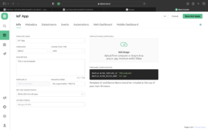
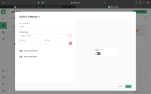
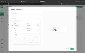
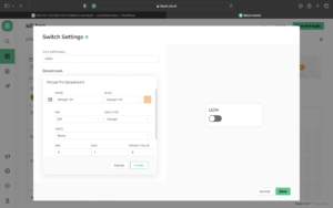
- Now when you log in the Blynk And just create the new Templates
- Just Select the Proper Board In this Project we used the ESP32 Board That’s why I selected the ESP32 Board With Wi-Fi.
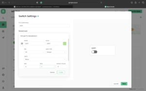
- Now We just add 4 switches because I turn them on and off For LEDs.
Demo Of Projects
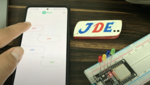
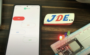
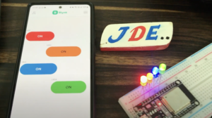
Now We just turn on the application and just turn on And Turn off The Switch
We just click the Switch1 And you see the Led Will Turn On
We Click the Switch2 the second LED Will be ON
We just click the Switch3 the Blue LED will be ON
Now We just Click the Switch4 The LED will Be ON
Video Tutorial
If you Interested in More ESP32 Projects

