Smart City Project Using Arduino
Overview
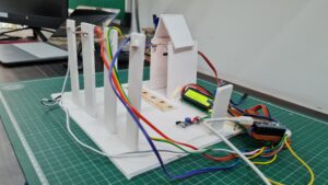
In This Project, I will Show You How to make a Smart City Using The Arduino Nano Board. I use the IR sensor, flame sensor and LDR sensor. the LDR sensor finds out the light density and is controlling the led light, the flame sensor fined out the fire, and the ir sensor Detect when any person comes To the home then is automatic gate will open and close.
In This Project, I used Multiple Sensor To Monitoring The Light Density, Fire Alert, Gate Open and Close Automated.
Bill Of Materials
S.N | Component | Quantity | Link To Buy |
1 | Arduino nano | 1 | |
2 | 16x2 LCD Display | 1 | |
3 | Sg-90 Servo Motor | 1 | |
4 | Led | 1 | |
5 | Buzzer | 1 | |
6 | IR Sensor | 1 | |
7 | LDR Sensor | 1 | |
8 | Fire Sensor | 1 | |
9 | Zero PCB | 1 |
Component’s For Smart City
Here I used the Arduino Nano Microcontroller board because it is low-cost and has many digital and analog pins available.
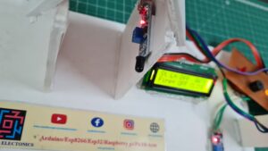
And I display All parameters to a 16×2 LCD display I mean if your light will on they LCD will display the on-and-off conduction, and also display the fire alter information.
IR Sensor
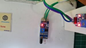
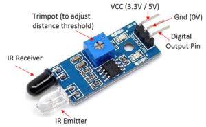
Here is IR Sensor Pin Diagram It operates in 5v and digital pin going to Arduino nano D3 Pin Number.
When Any Person crosses the IR Sensor the Servo Motor will gate open And Automatic Close The Door After a few Second.
LDR Sensor
LDR Sensor Is Light Dependent Sensor Is find Out the light Density in Digital format Light Density is More The LDR Given High Signal To Arduino Nano And if Light Density Is LOW Then The LDR Given LOW Signal To Arduino Nano Board.
LDR Sensor Will Be Connected To The Pin Number D11 to Arduino Nano Microcontroller
Flame Sensor
This one is the flame sensor pin Diagram and is used The Photodiode to detect the fire , is any fire conduction in the smart home then the flame sensor will be high and is given to signal to the Arduino board.
The flame Sensor will be connected to the Arduino nano D5 PinNumber.
If You Interested To More Arduino Project
- Vehicle Accident Alert System
- DIY Ventilator Using Arduino
- Arduino Based Blind Stick With GPS And GSM
- Dam Monitoring System Using Arduino
Block Diagram
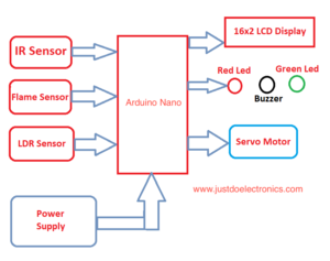
In this Block Diagram, I will show the input and output devices, Ir Sensor, Flame Sensor, And LDR Sensor they all Input devices And Output Sides I used the led for indication, LCD Display And Servo Motor.
I will give a 5v Dc Power supply with the Help Of a USB Cable Through In Arduino Nano Board.
Circuit Diagram
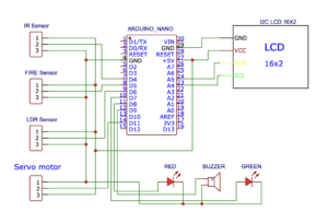
The Circuit diagram I will Design With the Help Of EasyEDA Software is Open Source online And Offline Tolls.
You just Select All the components properly way and do this connection and you just convert in PCB Layout Format.
In This Project, I Used 3 Digital sensors IR Sensor, LDR Sensor And Flame Sensor in Output Side I will Display All Sensor Information In a 16×2 LCD display.
I will Also Use The Red Led, Green Led And Piezo Buzzer and they will be Connected To The Pin Numbers D6, D7 And D8 in Arduino nano Board.
PCB Design
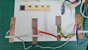
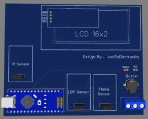
This Image Is the Final PCB Desing You just Print Out The PCB ANd Put All components in the given respectively slots.
Source Code
Before You Upload the code is first required to add The library first LiquidCrystal_I2C.h Then You Select the Proper Uploading Arduino Code.
|
1 2 3 4 5 6 7 8 9 10 11 12 13 14 15 16 17 18 19 20 21 22 23 24 25 26 27 28 29 30 31 32 33 34 35 36 37 38 39 40 41 42 43 44 45 46 47 48 49 50 51 52 53 54 55 56 57 58 59 60 61 62 63 64 65 66 67 68 69 70 71 72 73 74 75 76 77 78 79 80 81 82 83 84 85 86 87 |
#include <LiquidCrystal_I2C.h> LiquidCrystal_I2C lcd(0x27, 16, 2); const int flame = 5; int ir = 4; int ldr = 6; const int LED1 = 7; const int LED2 = 8; const int BUZZER = 9; void setup() { lcd.clear(); lcd.begin(); lcd.backlight(); lcd.setCursor(3, 0); lcd.print(" Welcome To"); lcd.setCursor(0, 1); lcd.print("JustDoElectronic"); pinMode(LED1, OUTPUT); pinMode(LED2, OUTPUT); pinMode(BUZZER, OUTPUT); delay(500); } void loop() { Sensor1(); Sensor2(); Sensor3(); delay(500); } void Sensor1() { int statusSensor1 = digitalRead(ldr); if (statusSensor1 == 1) { digitalWrite(LED1, HIGH); lcd.setCursor(0, 0); lcd.print("St.L = on."); } else { digitalWrite(LED1, LOW); lcd.setCursor(0, 0); lcd.print("St.L = off"); } } void Sensor2() { int statusSensor2 = digitalRead(ir); if (statusSensor2 == 1) { digitalWrite(LED2, HIGH); lcd.setCursor(13, 0); lcd.print("GATE"); lcd.setCursor(12, 1); lcd.print("OPEN"); } else { digitalWrite(LED2, LOW); lcd.setCursor(13, 0); lcd.print("GATE"); lcd.setCursor(12, 1); lcd.print("CLOSE"); } } void Sensor3() { int statusSensor3 = digitalRead(flame); if (statusSensor3 == 1) { digitalWrite(BUZZER, HIGH); lcd.setCursor(0, 1); lcd.print("Fire= ON"); } else { digitalWrite(BUZZER, LOW); lcd.setCursor(0, 1); lcd.print("Fire= OFF"); } } |


