Home Automation With Raspberry Pi Pico W
Introduction
Hi Welcome To Our Website www.justdoelectronics.com, In This Blog, I will Explain Raspberry Pi Pico Based Home Automation. You Used Any Pico Module Like Raspberry Pi Pico Or Raspberry Pi Pico W.Both one is the Same Just Different The Wifi module Raspberry Pi Pico W is on Board Wifi Module.
If You Don’t Know Much More About To Raspberry Pi Pico W Then Plz Watch The Blog Fist Click Here
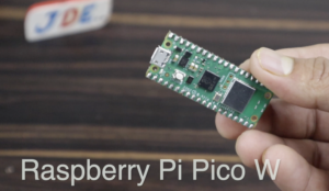
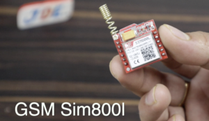
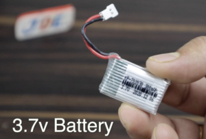
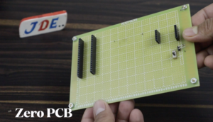
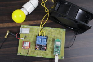
In This Project, I just used the Raspberry Pi Pico W Module, GSM Sim800l Module,2 Channel Module,3.7v Battery, Zero PCB And AC Load.
Our Project is working On the GSM(Global System for Mobile communication) When You Send a Text Message To Gsm Module SIM(Subscriber Identity Module) Card I Mean You Just Type LIGHT ON and send the GSM Module Received The Message And Turn On The LIGHT Relay If you Send Text Message To Again LIGHT OFF Gsm Module Received the Message And Turn Off The LIGHT Relay.
The same Conduction applies In A FAN Also You Type the Text Message FAN ON And Send GSM Received Message And Turn ON the Fan Relay you Type The Text Message FAN OFF And Send The GSM REcived Message And Turn Off The Fan Relay.
Raspberry Pi Pico W Pin Diagram:-
Bill of Materials
S.N | Component Name | Quanitity | Link To Buy |
1 | Raspberry Pi Pico W | 1 | |
2 | GSM Sim800l | 1 | |
3 | 2 Channel Relay Module | 1 | |
4 | 3.7 V Battery | 1 | |
5 | Zero PCB | 1 | |
6 | AC Fan | 1 |
Components
These All Are the component which I used In this Project.
Wesolderingg All Thecomponentst in This Zero PCB Like Raspberry Pi Pico , GSM Sim800l Module And Relay Modul.
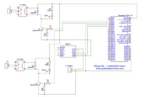
Circuit Diagram
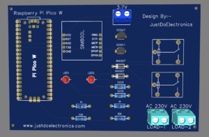
PCB Design
Here I Design The Pcb Using EasyEda Software, We just Put the Images Like Front Images of PCB, Back Images PCB,2D Images PCB And 3D Images of the PCB.
Source Code / Program
|
1 2 3 4 5 6 7 8 9 10 11 12 13 14 15 16 17 18 19 20 21 22 23 24 25 26 27 28 29 30 31 32 33 34 35 36 37 38 39 40 41 42 43 44 45 46 47 48 49 50 51 52 53 54 55 56 57 58 59 60 61 62 63 64 65 66 67 68 69 70 71 72 73 74 75 76 77 78 79 80 81 82 83 84 85 86 87 88 89 90 91 92 93 94 95 96 97 98 99 100 101 102 103 104 105 106 107 108 109 110 111 112 113 114 115 116 117 118 119 |
from machine import UART, Pin gsm_module = UART(1, baudrate=9600, tx=Pin(4), rx=Pin(5), timeout=2000) gsm_buffer = '' destination_phone = '+918830584864' relay1 = Pin(2, Pin.OUT) relay2 = Pin(3, Pin.OUT) def convert_to_string(buf): tt = buf.decode('utf-8').strip() return tt def do_action(msg): msg = msg.lower() if(msg.strip() == 'light off'): relay1(0) send_sms('light is OFF') elif(msg.strip() == "light on"): relay1(1) send_sms('light is ON') elif(msg.strip() == 'fan off'): relay2(0) send_sms('fan is OFF') elif(msg.strip() == 'fan on'): print('do_action1: '+msg) relay2(1) send_sms('fan is ON') def send_command(cmdstr, lines=1, msgtext=None): global gsm_buffer print(cmdstr) cmdstr = cmdstr+'\r\n' while gsm_module.any(): gsm_module.read() gsm_module.write(cmdstr) if msgtext: print(msgtext) gsm_module.write(msgtext) buf=gsm_module.readline() buf=gsm_module.readline() if not buf: return None result = convert_to_string(buf) if lines>1: gsm_buffer = '' for i in range(lines-1): buf=gsm_module.readline() if not buf: return result buf = convert_to_string(buf) if not buf == '' and not buf == 'OK': gsm_buffer += buf+'\n' return result def read_sms(sms_id): result = send_command('AT+CMGR={}\n'.format(sms_id),99) print(result) if result: params=result.split(',') if params[0] == '': return None params2 = params[0].split(':') if not params2[0]=='+CMGR': return None number = params[1].replace('"',' ').strip() date = params[3].replace('"',' ').strip() time = params[4].replace('"',' ').strip() #print('gsm_buffer:'+gsm_buffer) return [number,date,time,gsm_buffer] def send_sms(msgtext): global gsm_buffer result = send_command('AT+CMGS="{}"\n'.format(destination_phone),99,msgtext+'\x1A') if result and result=='>' and gsm_buffer: params = gsm_buffer.split(':') if params[0]=='+CUSD' or params[0] == '+CMGS': print('OK') return 'OK' print('ERROR') return 'ERROR' print(send_command('AT')) print(send_command('AT+CMGF=1')) print(send_command('AT+CNMI=1')) while True: if gsm_module.any(): buf=gsm_module.readline() buf = convert_to_string(buf) print(buf) params=buf.split(',') if params[0][0:5] == "+CMTI": msgid = int(params[1]) msg_data = read_sms(msgid) if not msg_data: print("No sms data found.") break print(msg_data[3]) if not msg_data[0] == destination_phone: print("Destination phone pumber not matching") break do_action(msg_data[3]) |
Here You Just Change The Mobile Number
|
1 |
destination_phone = '+918830584864' |
If you Want to Change the Message Format You just Change It here.
|
1 2 3 4 5 6 7 8 9 10 11 12 13 14 |
msg = msg.lower() if(msg.strip() == 'light off'): relay1(0) send_sms('light is OFF') elif(msg.strip() == "light on"): relay1(1) send_sms('light is ON') elif(msg.strip() == 'fan off'): relay2(0) send_sms('fan is OFF') elif(msg.strip() == 'fan on'): print('do_action1: '+msg) relay2(1) send_sms('fan is ON') |
Demo Of Project
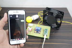
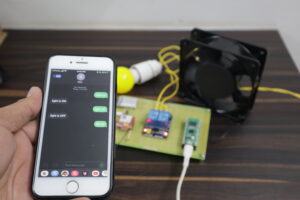
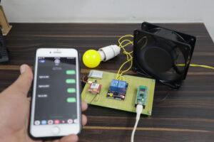
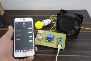
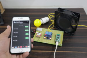
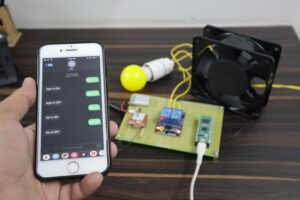
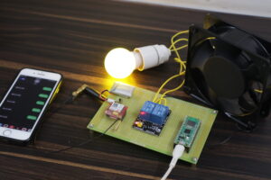
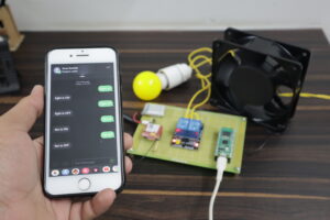
These All photos Show the Working of the project You Just See One By One.
You Just Type light on and Send the message to GSM Module
GSM Module Send The Feedback message light is On And The Light Will be ON
Just Send the Text Message light off
GSM Send the Feedback Message light is OFF and Our Light Will be OFF
Ok Now We Just Send the text message fan To GSM Module
GSM Module Send The Feedback Message fan is ON And You just see the fan it will be ON
Again GSM Send The Text Message fan off to GSM Module
GSM Module Received The Message And Sends the feedback Message fan is OFF And Fan Will be OFF
Video Tutorial
Result Of Project
This Is The all Hardware Of The Projects

