Temperature Based Fan Speed Controll
Temperature Based Fan Speed Controller Using Arduino & DHT11 Sensor
Introduction
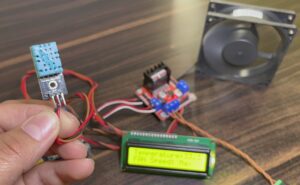
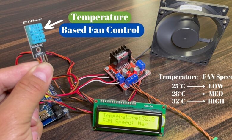
In This Article, We try to Build Temperature Based Fan Speed control with the Help Of the DHT11 Sensor If the Temperature crosses the Threshold Value Then the fan Speed is also changed according to the Code.
Here we used The Motor Driver L298N they control The DC Fan Speed According to the PWM Signal
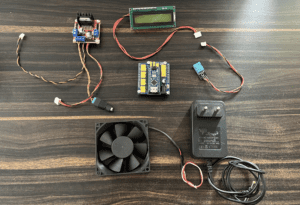
Bill Of Materials
S.N | Component's | Quantity | Link To Buy |
1 | Arduino Nano | 1 | |
2 | 16x2 LCD Display With I2C | 1 | |
3 | DHT11 Sensor | 1 | |
4 | L298N Motor Driver | 1 | |
5 | DC FAN | 1 | |
6 | 9v Power Supply | 1 |
Component’s Overview
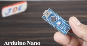
Arduino Nano
- The Arduino Nano is the open-source smallest Embedded Development board based on Atmega328 SMD Package Microcontroller.
- Arduino Nano is a low-cost microcontroller and so many GPIO Pin available.
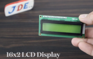
16×2 LCD Display
The 16×2 LCD Display is a basic 16-character by 2-line Alphanumeric display. White text on Blue background. Utilizes the extremely common HD44780 parallel interface chipset.
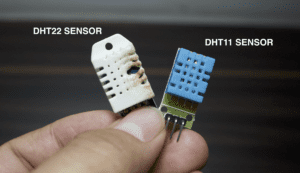
DHT11 Sensor
It has two sensing elements: a humidity sensor and a temperature sensor. Humidity elements find out the moisture present in the air, and temperature elements find out the temperature.
Specifications of the DHT11 sensor
- Temperature Range: 0°C to 50°C (32°F to 122°F).
- Temperature Accuracy: ±2°C.
- Humidity Range: 20% to 90%.
- Humidity Accuracy: ±5%.
- Resolution: 1°C for temperature measurements & 1% for humidity measurements.
- Response Time: 2 seconds for temperature readings & 2-5 seconds for humidity readings.
- Supply Voltage: 3.3V and 5V DC.
- Current Consumption: 1.5mA
- Communication: single-wire (Digital Sensor).
- Sampling Rate: 2 seconds.
L298N Motor Driver
This L298 Based Motor Driver Module is a high-power motor driver perfect for driving DC Motors and Stepper Motors. It uses the popular L298 motor driver IC and has the onboard 5V regulator to supply to an external circuit. It can control up to 4 DC motors.
Features:- Driver chip: L298 dual H-bridge driver chip. Operates up to 35V DC Drive part of the terminal’s peak current Io: 2A / Bridge Logical part.
- Power supply range Vss:4.5V-5.5V
- Operating current range: 0 ~ 36mA
- Maximum power consumption: 20W
Circuit Diagram
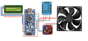
In this Circuit diagram, We Used The Arduino Nano Microcontroller And Controlling All The input and output Devices.
16×2 LCD Display Conected to the I2C Protocol Through That’s why required only 4 Wire
- SCL – A5
- SDA- A4
- VCC – 5v
- GND – GND
DHT11 Sensor Is Connected To the D7 Pin Number of Arduino nano Microcontroller
And The L298N Motor Driver Is Conected to the Pin NUmber D9, D10, D11.
The Hole Circuit works on 5v But the DC fan required the 12v DC Dource.
Code
|
1 2 3 4 5 6 7 8 9 10 11 12 13 14 15 16 17 18 19 20 21 22 23 24 25 26 27 28 29 30 31 32 33 34 35 36 37 38 39 40 41 42 43 44 45 46 47 48 49 50 51 52 53 54 55 56 57 58 59 60 61 62 63 64 65 66 67 68 69 70 71 72 73 74 75 76 |
//Prateek //www.justdoelectronics.com #include <Adafruit_Sensor.h> #include <DHT.h> #include <DHT_U.h> #include <Wire.h> #include <LiquidCrystal_I2C.h> #define DHTPIN 7 #define DHTTYPE DHT11 #define MOTOR_PIN_ENA 9 #define MOTOR_PIN_IN1 10 #define MOTOR_PIN_IN2 11 #define TEMPERATURE_THRESHOLD 28 #define TEMPERATURE_THRESHOLD1 32 DHT dht(DHTPIN, DHTTYPE); LiquidCrystal_I2C lcd(0x27, 16, 2); void setup() { Serial.begin(9600); dht.begin(); Wire.begin(); lcd.init(); lcd.backlight(); lcd.begin(16, 2); lcd.setCursor(0, 0); lcd.print("Temperature:"); } void loop() { delay(2000); float temperature = dht.readTemperature(); if (isnan(temperature)) { Serial.println("Failed to read temperature from DHT sensor!"); return; } Serial.print("Temperature: "); Serial.print(temperature); Serial.println(" °C"); lcd.setCursor(0, 1); lcd.print(" "); if (temperature > TEMPERATURE_THRESHOLD1) { analogWrite(MOTOR_PIN_ENA, 255); digitalWrite(MOTOR_PIN_IN1, HIGH); digitalWrite(MOTOR_PIN_IN2, LOW); lcd.setCursor(0, 1); lcd.print("FAN Speed: Max"); } else if (temperature > TEMPERATURE_THRESHOLD) { analogWrite(MOTOR_PIN_ENA, 100); digitalWrite(MOTOR_PIN_IN1, HIGH); digitalWrite(MOTOR_PIN_IN2, LOW); lcd.setCursor(0, 1); lcd.print("FAN Speed: Med"); } else { analogWrite(MOTOR_PIN_ENA, 45); digitalWrite(MOTOR_PIN_IN1, HIGH); digitalWrite(MOTOR_PIN_IN2, LOW); lcd.setCursor(0, 1); lcd.print("FAN Speed: Low"); } lcd.setCursor(12, 0); lcd.print(temperature); } |
Demo Of Projects
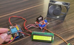
If the Temperature is LOW Then the Fan Speed is Less.
If the Temperature Cross the Threshold Value 1(28°C) Then FAN Speed is MED.
If the Temperature Cross the Threshold Value 2(32°C) Then the FAN Speed is HIGH.
Video Tutorial
Conclusion
In this project, we used a DC Fan And the Speed Control With The PWM Signal Through. The Conduction Will be displayed in the 16×2 LCD Display.
