
Small GPS Tracker using arduino
how to make a small gps tracker using arduino pro mini
Introduction
In this article, we make a small GPS tracking device using Arduino pro mini. this device includes a Lithium iron battery that provides 3.7v to Arduino Pro mini. you easily track any location when you press the push button the gsm module sends the proper GPS link to the particular mobile number.
Components
Here we used a few components and why I used them in this project that’s I explain it.
Arduino pro mini
Here we used the Arduino Pro mini the controlling the input and output device like when you press the push button the digital signal goes to the digital pin and the response the gsm through after a few second the gsm send the proper text message with GPS location.
Specifications and Features
- Operating Voltage: 5V
- Clock frequency: 16MHz.
- Digital I/O Pins: 14
- 8 analog input ports: A0 ~ A7.
- A pair of TTL-level serial port transceivers: RX / TX.
- 6 PWM port: D3, D5, D6, D9, D10, D11.
- IC Used Atmel Atmega328P-AU microcontroller.
- Support serial download.
- Support 9V battery.
- Package Includes :
- 1 x Pro mini 5v/16mHZ compatible
GSM SIM800l
Sim800l GSM Module is a small type of gsm module and its operating voltage is 3.7v to 4.4v you used a lithium-ion battery.
- GSM is used for sense text messages we just connected the Rx And Tx Pin of Arduino Serail Tx And Rx Pin.
- GSM GND Pin connected to the Arduino pro mini GND Pin.
- And The VCC Pin is connected to the lithium-ion battery (3.7v) And is important that the GND Pin is connected to the Arduino Pro mini GND Pin.
- Quad-band 850/900/1800/1900MHz – connect onto any global GSM network with any 2G,3G And 4G SIM (in India, JIO is not supported).
- Make and receive voice calls using a headset or an external 8Ω speaker and electret microphone.
- AT command interface with “auto baud” detection
- Send and receive SMS messages.
- Send and receive GPRS data (TCP/IP, HTTP).
NZ Mini GPS Module
NZ Mini GPS module is also small in size and is better for indoor and outdoor. the operating voltage is 3.7v to 5v you are directly connected to the Arduino Pro min 5v pin.
Features
- Dimensions: 26 x 25 x 8 mm(LxWxH).
- Weight: 10gm.
- Cable Length: 15cm.
- NZ GPS Suitable for Flight Controller NAZE 32, Interface 1 Pin 2.54.
- This GPS is customized for the Naze32 flight controller.
- Internal Ublox 7 series chip core of manufacture OEM.
- Super mini size
- weight only 10g
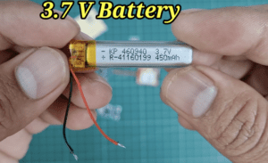
3.7v Battery
- this one is a lithium-ion battery and is perfect for this project and is also sufficient for the SIM800l GSM Module.
Tp4056 Charging Module
TP4056 1A Li-Ion Battery Charging Board with Current Protection is a tiny module, perfect for charging single cell 3.7V 1 Ah or higher lithium-ion (Li-Ion) cells such as 16550s that don’t have their own protection circuit.
Specifications
- Charging accuracy (%) 1.5
- Charging method Linear
- Full Charge Voltage (V) 4.2
- Over-Current Protection (A) 3
- Voltage Protection (V) 2.5
- Input Voltage (V) 4.2-5
- Rated Power (W) 4
- Operating Temperature (°C) -10 to 85
Switch
the sliding switch controls the battery supply if you want then turn on the switch and if you do not want to track the location just turn off the switch.
Push Button
this one is 2 pin push button
Circuit diagram
GSM module connections
- VCC pin of the GSM module connected to the 5V pin of the Arduino.
- GND pin of the GSM module connected to the GND pin of the Arduino.
- TX pin of the GSM module connected to the digital input pin on the Arduino (7).
- RX pin of the GSM module connected to the digital output pin on the Arduino (8).
GPS module connections
- VCC pin of the GPS module connected to the 5V pin of the Arduino.
- GND pin of the GPS module connected to the GND pin of the Arduino.
- TX pin of the GPS module connected to the digital input pin on the Arduino (Rx).
- RX pin of the GPS module connected to the digital output pin on the Arduino (Tx).
- Connect a push button to pin 10 of the Arduino Pro Mini.
Code
Before uploading just Change the number
|
1 |
char phone_no[] = "+91xxxxxxxxxx"; |
We Just Add the Library and change the Mobile Number then you upload the Code
|
1 2 3 4 5 6 7 8 9 10 11 12 13 14 15 16 17 18 19 20 21 22 23 24 25 26 27 28 29 30 31 32 33 34 35 36 37 38 39 40 41 42 43 |
//Prateek //www.justdoelectronics.com #include <TinyGPS.h> #include <SoftwareSerial.h> #include <Wire.h> SoftwareSerial Gsm(7, 8); char phone_no[] = "+91xxxxxxxxxx"; TinyGPS gps; int state; String textMessage; void setup() { Serial.begin(9600); Gsm.begin(9600); Serial.print("AT+CMGF=1\r"); delay(100); Serial.print("AT+CNMI=2,2,0,0,0\r"); delay(100); pinMode(10, INPUT); } void loop() { bool newData = false; unsigned long chars; unsigned short sentences, failed; for (unsigned long start = millis(); millis() - start < 1000;) { while (Serial.available()) { char c = Serial.read(); Serial.print(c); if (gps.encode(c)) newData = true; } } if (Gsm.available() > 0) { textMessage = Gsm.readString(); textMessage.toUpperCase(); delay(10); } //Prateek //www.justdoelectronics.com Serial.println(failed); } |
- When You Press the Push Button This Condition Will Happen
|
1 2 3 4 5 6 7 8 9 10 11 12 13 14 15 16 17 18 19 20 21 22 23 24 25 26 27 28 29 30 31 32 33 34 35 36 37 38 |
state = digitalRead(10); if (state == 0) //Prateek //www.justdoelectronics.com { float flat, flon; unsigned long age; gps.f_get_position(&flat, &flon, &age); Gsm.print("AT+CMGF=1\r"); delay(400); Gsm.print("AT+CMGS=\""); Gsm.print(phone_no); Gsm.println("\""); Gsm.println("Alert I need help............."); Gsm.print("http://maps.google.com/maps?q=loc:"); Gsm.print(flat == TinyGPS::GPS_INVALID_F_ANGLE ? 0.0 : flat, 6); Gsm.print(","); Gsm.print(flon == TinyGPS ::GPS_INVALID_F_ANGLE ? 0.0 : flon, 6); delay(200); Gsm.println((char)26); //Prateek //www.justdoelectronics.com delay(200); Gsm.println(); Serial.println("SMS Sent"); Serial.println("Call"); delay(20000); Gsm.println("ATD+91xxxxxxxxxx;"); delay(150000); Gsm.println("ATH"); delay(1000); } else { delay(10); } |
Project working demo
Here is a few photos of how the project will work see when I press the push button then after a few second the mobile received a text message with GPS Coordinates.
- see the all hardware part which one we used for the projects, this one is relay working well and is used in various fields.
- if GPS does not get the proper signal then go outside wait for a few seconds and when GPS blue light is blynk then the GPS get the signal and is working properly.
Video
More GPS Tracker Projects




Nice GPS Tracker project. It would be great if you can share the PCB files.