sim800l gsm module arduino tutorial
send receive SMS&Call with SIM800L GSM Module & Arduino
Introduction
In this article, we explain how the sim800l GSM/GPSRS module will work and how you can use it in any IoT project. You can use this module and do almost all phone calls and SMS Message Projects, and you also use it for GPRS BAsed Projects.
if you are interested in more about the GSM SIM800L Module Plz Go through the Datasheet.
Bill Of Material
S.N | Component's | Quantity |
1 | Arduino Nano | 1 |
2 | SIM800l GSM Module | 1 |
3 | 3.7v Battery | 1 |
4 | 3.7v Battery Holder | 1 |
5 | Zero PCB | 1 |
6 | PUSH On/Off Switch | 1 |
7 | Antenna | 1 |
Hardware Overview
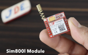
The Heart of the module is a SIM800l GSM cellular chip from the simcom attachment.
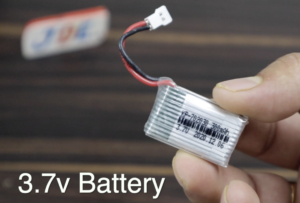
- The operating voltage of the chip ranges from 3.4v to 4.4v you used a direct LiPo Battery supply and a 3.7v lithium-ion battery.
- Is a really small size GSM Module and its operating voltage is also low.it is better for embedding projects.
The Module requires an external antenna to connect to the network. so the module comes with a helical antenna that can be soldered to it. but this board also has a UFL connector if you use it then you get a better signal.
There is a SIM Socket on the back any 2G, or 3G SIM card will work properly. it proper way to insert the SIM Card is typically engraved on the surface of the SIM Socket.
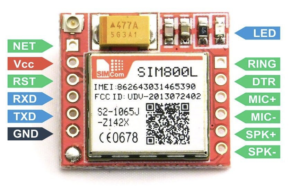
The SIM800L Module has a total of 12 Pins
VCC Pin:- is a power supply pin you connect to the 3.4v to 4.4v power supply with the help of a lithium-ion battery or LM2596 Step Down Converter.
RST Pin:- is the reset pin. if you do not get a signal in a bad space then pull this pin LOW for 100ms to hard reset.
RxD Pin:- pin is used to send commands to the module. if your baud rate is a match then you send the AT Command easily.
TxD Pin:– is a pin used to transmit data from the module to the controller.
GND Pin:- is the ground pin to connect to the controller.
RING Pin:- indicates the Ring Alert is the interrupt-out pin from the module. when you receive an SMS or Call the PIN is LOW.
DTR Pin:- is control the sleep mode is not SMS And Call Come then GSM module go in Sleep Mode.
MIC Pin:- is connected to the microphone input You can connect an external microphone is 2 pins directly.
SPK Pin:- is connected to the Speaker. You can connect to a PIN speaker directly
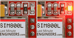
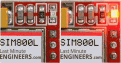
The Sim800l Module has an LED that indicates the status of your cellular network.is blinking different patterns depending on the cellular network state.

Here we used the 3.7v battery to give proper supply to the SIM800L GSM Module and is Working Perfectly.
And if you did not use a battery then there is another option available you use the LM2596 Step Down Conveter On the input side you are given a 9V or 12V supply and output side you set the 3.7V only.
Circuit Diagram
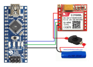
Wiring A SIM800L GSM Modle to the Arduino nano microcontroller and attach the 3.7v battery to the batter supply.
The GSM Connected to the UART Protocol
For Arduino D2 Pin connected to the gsm Tx Pin and Arduino D3 Pin Connected to the gsm Rx Pin and both ground pin is common
Code
Here we used the Arduino IDE software to upload the code to send AT commands and communicate with the SIM800l module. we used the serial monitor.
|
1 2 3 4 5 6 7 8 9 10 11 12 13 14 15 16 17 18 19 20 21 22 23 24 25 26 27 28 29 30 31 32 33 34 35 36 37 38 39 40 41 42 43 |
#include <SoftwareSerial.h> SoftwareSerial mySerial(2, 3); void setup() { Serial.begin(9600); mySerial.begin(9600); Serial.println("Initializing..."); delay(1000); mySerial.println("AT"); updateSerial(); mySerial.println("AT+CMGF=1"); updateSerial(); mySerial.println("AT+CMGS=\"+918830584864\""); // enter your phone number here (prefix country code) updateSerial(); mySerial.print("Hello From justdoelectronics"); // enter your message here updateSerial(); mySerial.write(26); } void loop() { } void updateSerial() { delay(500); while (Serial.available()) { mySerial.write(Serial.read()); } while(mySerial.available()) { Serial.write(mySerial.read()); } } |
Code_2
|
1 2 3 4 5 6 7 8 9 10 11 12 13 14 15 16 17 18 19 20 21 22 23 24 25 26 27 28 29 30 31 32 33 34 35 36 37 38 39 40 41 42 43 44 45 46 47 48 49 50 51 52 53 54 55 56 57 58 59 60 61 62 63 64 65 66 67 68 69 70 71 72 73 |
#include <SoftwareSerial.h> SoftwareSerial sim(2, 3); int _timeout; String _buffer; String number = "+918830584864"; void setup() { delay(7000); Serial.begin(9600); _buffer.reserve(50); Serial.println("Sistem Started..."); sim.begin(9600); delay(1000); Serial.println("Type s to send an SMS, r to receive an SMS, and c to make a call"); } void loop() { if (Serial.available() > 0) switch (Serial.read()) { case 's': SendMessage(); break; case 'r': RecieveMessage(); break; case 'c': callNumber(); break; } if (sim.available() > 0) Serial.write(sim.read()); } void SendMessage() { Serial.println("Sending Message"); sim.println("AT+CMGF=1"); delay(1000); Serial.println("Set SMS Number"); sim.println("AT+CMGS=\"" + number + "\"\r"); delay(1000); String SMS = "Hi I am Prateek"; sim.println(SMS); delay(100); sim.println((char)26); delay(1000); _buffer = _readSerial(); } void RecieveMessage() { Serial.println("SIM800L Read an SMS"); delay(1000); sim.println("AT+CNMI=2,2,0,0,0"); delay(1000); Serial.write("Unread Message done"); } String _readSerial() { _timeout = 0; while (!sim.available() && _timeout < 12000) { delay(13); _timeout++; } if (sim.available()) { return sim.readString(); } } void callNumber() { sim.print(F("ATD")); sim.print(number); sim.print(F(";\r\n")); _buffer = _readSerial(); Serial.println(_buffer); } |
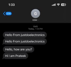
 Working Demo
Video
Conclusion
The GSM SIM800L Module works perfectly but if you are not given the proper supply and do not use the proper antenna then it will not work.in most projects, we used the sim800l module because is small in size and also low cost.
