Real Time GPS Tracker Using NodeMCU
Introduction
In this article, we will guide you through the process of creating a real-time GPS location tracker using NodeMCU, a 16×2 LCD display, and a Neo6m GPS module. With the all components and the Blynk app, you will be able to track the GPS coordinates of your device. Let’s Make the projects step-by-step.
Component Need
- NodeMCU (ESP8266 Development Board)
- Neo6m GPS module
- 16×2 LCD display with I2C
- Wires
- Zero PCB
- USB cable for NodeMCU
NodeMCU
ESP8266 is a Wi-Fi module developed by Espressif Microcontroller Systems. In the board is a microcontroller unit And a built-in Wi-Fi Chip, It is the low-cost solution for Wi-Fi connectivity to various projects.
- Microcontroller: The module is a 32-bit microcontroller, which operates at 80 MHz clock speed. It provides a few GPIO (General Purpose Input/Output) pins that can be used to interface with L298N Motor Driver and Wifi.
- Wi-Fi Connectivity: The module supports 2.4 GHz And Wi-Fi 802.11 b/g/n standards, allowing it to connect to Wi-Fi networks and Also communicate over the internet.
- Memory: The module typically comes with different memory configurations. It has built-in flash memory for program storage and data storage.
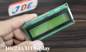
16×2 LCD Display With I2C
A 16×2 LCD display with an I2C interface with ESP8266 Microcontroller they used only four vin VCC, GND, SDA And SCL.The LCD module consists of a 16-character by 2-line alphanumeric display.
- LCD Display: The LCD (Liquid Crystal Display) module is a common output device used to display messages.
- I2C Expander: The PCF8574 or MCP23008, I2C LCD module expander. The I2C expander expands the number of available GPIO pins, allowing the microcontroller to control the LCD with fewer pins.
GPS NEO 6m Module
The GPS NEO-6M module is a commonly used GPS (Global Positioning System) module. It provides accurate positioning, navigation, and timing information by receiving signals from multiple satellites orbiting the Earth.

- GPS Receiver: The NEO-6M module is equipped with a GPS receiver chip that processes signals from GPS satellites. It uses a combination of satellite signals to determine its precise location, altitude, speed, and time.
- Satellite Tracking: The NEO-6M module can track multiple GPS satellites simultaneously. By receiving signals from several satellites, it can calculate the receiver’s position accurately using trilateration techniques.
- Communication Interface: The module communicates with a microcontroller or a computer using serial communication. It typically employs UART (Universal Asynchronous Receiver-Transmitter) protocol, allowing the microcontroller to send commands and receive GPS data.
- Power Supply: The module requires a power supply voltage typically ranging from 3.3V to 5V. It is important to provide a stable power source to ensure reliable operation.
- Antenna: The NEO-6M module requires an external GPS antenna to receive signals from GPS satellites. The antenna should be placed in an open area to ensure a clear view of the sky for better signal reception.
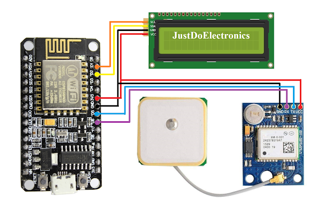
Circuit Diagram
- Connect the VCC and GND pins of the NodeMCU to the respective power and ground.
- Connect the SDA (data) and SCL (clock) pins of the NodeMCU to the corresponding pins on the I2C interface of the LCD module.
- Connect the VCC and GND pins of the LCD module to the power and ground rails.
- Connect the TX and RX pins of the Neo 6m GPS module to the RX and TX pins of the NodeMCU, respectively.
- Connect the VCC and GND pins of the Neo 6m module to the power and ground rails.
Blynk App
A “Blank App” typically refers to a software application that has a minimal or empty user interface and lacks any predefined functionality or features. It serves as a starting point or template for developers to build upon and customize according to their specific requirements. The purpose of a blank app is to provide a clean slate, allowing developers to implement their desired functionalities and design elements from scratch.
Check the Full Video on How to set up Blynk App
Code
Software Setup
- First we Install the Arduino IDE on your computer.
- Open the Arduino IDE and go to “File” -> “Preferences”.
- In the “Additional Boards Manager URLs” field, enter the following URL and click “OK”: http://arduino.esp8266.com/stable/package_esp8266com_index.json
- Go to “Tools” -> “Board” -> “Boards Manager”.
- Search for “esp8266” and install the “esp8266” board.
- Once the installation is complete, select the “NodeMCU” board from the “Tools” -> “Board” menu.
Install the required libraries
|
1 2 3 4 5 6 7 8 9 10 11 12 13 14 15 16 17 18 19 20 21 22 23 24 25 26 27 28 29 30 31 32 33 34 35 36 37 38 39 40 41 42 43 44 45 46 47 48 49 50 51 52 53 54 55 56 57 58 59 60 61 62 63 64 65 66 67 68 69 70 71 72 73 74 75 76 77 |
//Prateek //https://justdoelectronics.com //https://www.youtube.com/c/JustDoElectronics/videos #include <SoftwareSerial.h> #define BLYNK_PRINT Serial #include <TinyGPS++.h> #include <ESP8266WiFi.h> #include <BlynkSimpleEsp8266.h> const int RXPin = 4, TXPin = 5; const uint32_t GPSBaud = 9600; SoftwareSerial gps_module(RXPin, TXPin); TinyGPSPlus gps; WidgetMap myMap(V0); BlynkTimer timer; float gps_speed; float no_of_satellites; String satellite_orientation; char auth[] = "xxxxxxxxxxxxxxxxx"; char ssid[] = "justdoelectronics"; char pass[] = "123456789"; unsigned int move_index = 1; void setup() { Serial.begin(115200); Serial.println(); gps_module.begin(GPSBaud); Blynk.begin(auth, ssid, pass); timer.setInterval(5000L, checkGPS); } void checkGPS() { if (gps.charsProcessed() < 10) { Serial.println(F("No GPS detected: check wiring.")); Blynk.virtualWrite(V4, "GPS ERROR"); } } void loop() { while (gps_module.available() > 0) { if (gps.encode(gps_module.read())) displayInfo(); } Blynk.run(); timer.run(); } void displayInfo() { if (gps.location.isValid()) { float latitude = (gps.location.lat()); float longitude = (gps.location.lng()); Serial.print("LAT: "); Serial.println(latitude, 6); Serial.print("LONG: "); Serial.println(longitude, 6); Blynk.virtualWrite(V1, String(latitude, 6)); Blynk.virtualWrite(V2, String(longitude, 6)); myMap.location(move_index, latitude, longitude, "GPS_Location"); gps_speed = gps.speed.kmph(); Blynk.virtualWrite(V3, gps_speed); no_of_satellites = gps.satellites.value(); Blynk.virtualWrite(V4, no_of_satellites); satellite_orientation = TinyGPSPlus::cardinal(gps.course.value()); Blynk.virtualWrite(V5, satellite_orientation); } Serial.println(); } |
Video
Conclusion
By following this tutorial, you have successfully built a real-time GPS location tracker using NodeMCU, a 16×2 LCD display, and a Neo6m GPS module. The integration of the Blynk app allows you to conveniently track your device’s live GPS coordinates. This project can have various applications, such as vehicle tracking, asset monitoring, or personal tracking. Explore further possibilities and enhance the functionality according to your needs.
GPS Related More Projects


