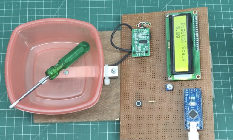
Load Cell & HX711 Module With Arduino Nano
Arduino Digital Weight Scale HX711 Load Cell Module
Introduction
Hi, in this tutorial, we will be making a weight sale machine using a load cell and Hx711 module. The load cell sensor generates a proportional electrical signal to the weight applied to it.
Hx711 amplifier converts the analog signal to a digital value that Arduino Nano can understand. First, we calibrate the load cell and Hx711 amplifier then the load cell measures the proper weight on which one you put the object in the load cell.
if you interested in more Arduino Tutorial
Bill of Materials
S.N | Component | Quantity | Link To Buy |
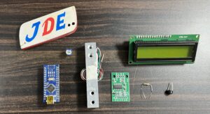
1 | Arduino Nano | 1 | |
2 | 16x2 LCD Display | 1 | |
3 | 10kg Load Cell | 1 | |
4 | HX711 Module | 1 | |
5 | 10k Pot | 1 | |
6 | Push Button | 1 | |
7 | Zero PCB | 1 | |
8 |
Component
Arduino nano
Arduino Nano is Also a Small Microcontroller and its operating voltage is 3.3v To 5v. This Microcontroller is supported by USB2.0 Mini B To USB2.0A.
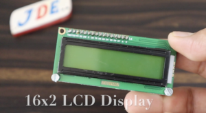
16×2 LCD Display
16×02 LCD type with 2 rows of 16 Columns. This model operates at 5V and has a green backlight with white-on-Green text. It features a standard HD44780 compatible controller to simplify integration into your project and includes a strip of male header that can be soldered to the board as needed.
10k Pot
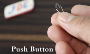
Push Button
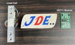
Load Cell & HX711 Module
Load Cell
The load cell is a module for measuring the force. they are used in varial fields, industrial, weight machines & medical applications to measure the weight of an object, the force exerted by the fluid on a surface. a load cell is made of metal Saft by an inbuilt strain gauge. When force is applied to the beam, the strain gauge measuring the resulting distortion of the beam produces a signal that the proportional to the force.
Specifications
- Capacity – 10kg
- Accuracy – 0.03% Fs
- Output – 4 wires (Whcalshone bride)
- Method of connecting wire – Red(+), Black(-), Green(+), White(-)
- Zero output – 0.05% fs
HX711 Load Cell Amplifier
This deuce is used to measure the force exerted by an object. The module interfacing with the load cell and Arduino Nano microcontroller are easy to read reading & it is reading the whetstone bridge formed by the load cell. Converting the analog reading to Digital form with an internal 24-bit A/D converter.
To communicate the Hx711 Amplifier circuit with Arduino Nano pin (clock & Date) in a serial way. (similar to I2C)
In 4 4-wire Arough, we could to Hx711 module to load cells, Red, Black, White & Green.
- Red – Excitation Voltage(+), E+, VCC
- Black – Excitation Voltage (-), E-, GND
- Green – Amplifier (-), Signal (-), A(-)
- White – Amplifier (+), Signal (+), A(+)
Specifications
- Operating Voltage – 2.7V to 5V DC
- Operating voltage – 710 mA
- Refresh frequency – 10/90 HZ
- Data Accularly – 24-bit ( A/D converter chip)
Zero PCB
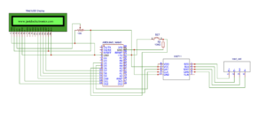
Circuit Diagram
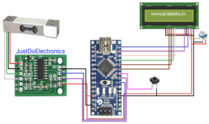
Do The Hardware Connection
Load cell – Hx711
- Red (E+) – E+
- Black (E-) – E-
- White(A-) – A-
- Green(A+) – A+
Hx711 – Arduino Nano
- GND – GND
- DT – D5
- SLK – D4
- VCC – 5v
16×2 LCD – Arduino Nano
- VSS – Ground
- VCC – 5V
- VEE – Contrast adjust
- RS Data/command select (data=high, command=low) – D12
- R/W Read/write select (read=high, write=low) – GND
- E Enable – D11
- DB0 Data bit – X
- DB1 Data bit – X
- DB2 Data bit – X
- DB3 Data bit – X
- DB4 Data bit – D10
- DB5 Data bit – D9
- DB6 Data bit – D8
- DB7 Data bit – D7
- LED(+) – Backlight – 5V
- LED(-) – GND
Push Button Interfacing With – D6
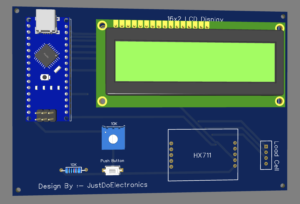
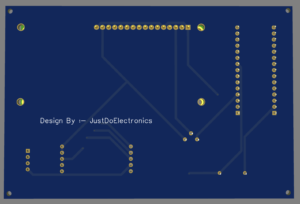
PCB Design
Installing the HX711 Library
There are many sources to get measurements from a load cell using the HX711 amplifier. We’ll use the HX711 library. It is compatible with Arduino, ESP32, and ESP8266.
Now Upload the final Code….
|
1 2 3 4 5 6 7 8 9 10 11 12 13 14 15 16 17 18 19 20 21 22 23 24 25 26 27 28 29 30 31 32 33 34 35 36 37 38 39 40 41 42 43 44 45 46 47 48 49 50 51 52 53 54 55 56 57 58 59 60 61 62 63 64 65 66 67 68 |
//Prateek //wwww.justdoelectronics.com //https://www.youtube.com/c/JustDoElectronics/videos #include <HX711_ADC.h> #include <Wire.h> #include <LiquidCrystal.h> LiquidCrystal lcd(12, 11, 10, 9, 8, 7); HX711_ADC LoadCell(5, 4); // DT , SCK int taree = 6; int a = 0; float b = 0; void setup() { pinMode(taree, INPUT_PULLUP); LoadCell.begin(); LoadCell.start(1000); LoadCell.setCalFactor(375); lcd.begin(16, 2); lcd.setCursor(1, 0); lcd.print("Digital Scale "); lcd.setCursor(0, 1); lcd.print(" 10KG MAX LOAD "); delay(3000); lcd.clear(); } void loop() { lcd.setCursor(1, 0); lcd.print("Digital Scale "); LoadCell.update(); float i = LoadCell.getData(); if (i < 0) { i = i * (-1); lcd.setCursor(0, 1); lcd.print("-"); lcd.setCursor(8, 1); lcd.print("-"); } else { lcd.setCursor(0, 1); lcd.print(" "); lcd.setCursor(8, 1); lcd.print(" "); } lcd.setCursor(1, 1); lcd.print(i, 1); lcd.print("g "); float z = i / 28.3495; lcd.setCursor(9, 1); lcd.print(z, 2); lcd.print("oz "); if (i >= 5000) { i = 0; lcd.setCursor(0, 0); lcd.print(" Over Loaded "); delay(200); } if (digitalRead(taree) == LOW) { lcd.setCursor(0, 1); lcd.print("Load Reset"); LoadCell.start(1000); lcd.setCursor(0, 1); lcd.print(" "); } } |
Demo of Project
Before putting weight on the load cell
After putting weight on the load cell
