Introduction
Hi Everyone I Know you have learned so much about Arduino, But I will try to Explain Arduino in My Knowledge If You Learn Anything in This Article Please Comment Below…..
Arduino is an Open-source Platform And is Very Easy To Learn The Microcontroller, In first time Developed in Italy.
If You Want To Download the Software https://www.arduino.cc/en/software

In the Market is Various Types Of Arduino Available Like Arduino Lilypad, Arduino Micro, Arduino Nano, Arduino PRO Mini, Arduino UNO, Arduino Mega2560, ETC…….
Types Of Board
1. Arduino Pro-Mini
Arduino pro-mini is a small microcontroller and its operating voltage is 3.3V To 5v.

S.N. | Features | Value |
1 | Microcontroller IC | Atmega328 |
2 | Digital Input/Output | 14 (D0-D13) |
3 | Analog | 8 (A0-A7) |
4 | PWM Pins | 6 |
5 | USB Port | Not Available |
6 | Built In Programmer | Not Available |
7 | SRAM | 2KB |
8 | EEPROM | 1KB |
9 | Flash Memory | 32KB |
10 | Bootloader | 0.5KB In Flash Memory |
11 | Operating Voltage | 3.3V To 5V |
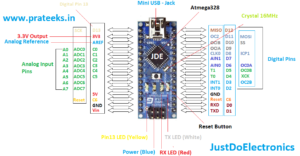
2. Arduino Nano
Arduino Nano is Also a Small Microcontroller and its operating voltage is 3.3v To 5v. This Microcontroller is supported by USB2.0 Mini B To USB2.0A.

S.N. | Feature | Value |
1 | Microcontroller IC | ATmega328p |
2 | Digital Input/Output Pin | 14 (D0-D13) |
3 | Analog Pin | 8 (A0-A7) |
4 | PWM Pin | 6 |
5 | Built In Progammer | Yes |
6 | USB port | Yes Avilable (Type-B Micro Usb) |
7 | flash Memory | 32KB |
8 | SRAM Memory | 2KB |
9 | EEPROM | 1KB |
10 | Crystal Oscillator | 16 MHz |
11 | Operating voltage | 5V |
3.Arduino UNO
Arduino UNO is the Best Board To start programming with Arduino IDE. This Microcontroller is Supported by The Dip Ic (ATmega328Pu IC), And The Operating Voltage is 3.3V, 5V or 9V.
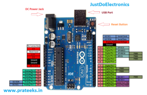
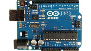
Arduino UNO Is Available in the market With DIP IC and SMD IC.

S.N. | Feature | Value |
1 | Microcontroller IC | Atmega328p |
2 | Digital Input/Output Pin | 14 (D0-D13) |
3 | Analog Pins | 8 (A0-A8) |
4 | PWM Pins | 6 |
5 | USB Port | Yes (USB-A To USB-B) |
6 | Flash memory | 32KB |
7 | SRAM | 2KB |
8 | EEPROM | 1KB |
9 | Crystal Oscillator | 16MHz |
10 | Operating voltage | 5v To 9V |
11 | ICSP Header | Yes |
4. Arduino Mega
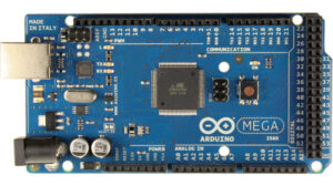
This Board Is not Small and is very fast Various pins are Available
. Arduino Mega is Advanced Level Microcontroller And is Supported USB Programming, Operating voltage is 3.3V To 12v.
S.N. | Features | Value |
1 | Microcontroller IC | Atmega2560 |
2 | Digital Input/Output Pins | 54 |
3 | Analog Pins | 16 |
4 | PWM Pins | 15 |
5 | Built in programming | yes |
6 | USB Port | Yes (USB-A To USB-B) |
7 | Flash Memory | 256KB |
8 | SRAM | 8KB |
9 | EEPROM | 4KB |
10 | Crysatl Oscillator | 16 MHz |
11 | ICSP Header | Yes |
Introduce Arduino IDE Software
I Will already Share the Arduino IDE Software Link https://www.arduino.cc/en/software You just Download the software And Open it Depending on your Operating System.
Explanation IDE
Just install the Software and open It then you sell like this ….

you just open the IDE And go to the tools and you see the different Boards Available, You Just Select the board Correctly
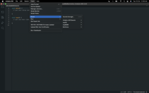
On the Left Side, you see the verify and upload Symbol Available
- if you type the code in the editor and you want to check whether the code will generate an error or not you just click the verify button then our code will compile and find the error.
- if you want to Upload the code in the microcontroller you just click the Uploading Button first you select the proper board and port.
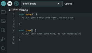
On the Right Side, You just see the corner of the Serial monitor and Serial Plotter Available

Started With Arduino Nano Board
Arduino Nano With Serial Monitor
Here I Just Interface the Arduino Nano Board With Arduino IDE Software And I just write the code and Display the output in Serial Monitor.

|
1 2 3 4 5 6 7 8 9 10 |
void setup() { Serial.begin(9600); } void loop() { Serial.println("Hi Welcome To JustDoElectronics"); } |
1. Led Interfacing With Arduino Nano
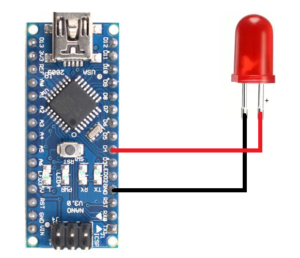
Here I just interfacing with Arduino Nano Board

I will connect the LED in PIN D4
- Anode – D4
- GND – GND
Code
|
1 2 3 4 5 6 7 8 9 10 11 12 |
//Prateek //www.justdoelectronics.com void setup() { pinMode(D4, OUTPUT); } void loop() { digitalWrite(D4, HIGH); delay(1000); digitalWrite(D4, LOW); delay(1000); |
2. Push Button Interfacing With Arduino Nano
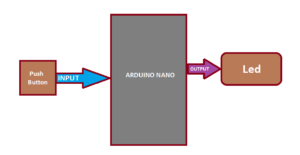
Here I just interfacing the push Button, Led with an Arduino nano Board
The input Side is Connected to the push Button and the output side will glow the LED, when the button is pressed the LED will be ON and if you release the push button then the LED will be OFF.
Circuit Diagram
|
1 2 3 4 5 6 7 8 9 10 11 12 13 14 15 16 17 18 19 20 21 22 23 24 25 26 27 28 29 30 31 32 33 34 35 |
//Prateek //www.justdoelectronics.com #define SWITCH_PIN 3 #define LED_PIN 12 int switchState; // To store the state of switch void setup() { // Set pin and D3 as input pinMode(SWITCH_PIN, INPUT); // Set pin D12 as output pinMode(LED_PIN, OUTPUT); // Turn off the LED initially digitalWrite(LED_PIN, LOW); } void loop() { // Read the states of the switches switchState = digitalRead(SWITCH_PIN); // Check if switch is pressed if (switchState == HIGH) { // Turn on LED digitalWrite(LED_PIN, HIGH); } else { // Turn off LED digitalWrite(LED_PIN, LOW); } // Delay for 100 milliseconds delay(100); } |
3. Potentiometer Interfacing With Arduino Nano
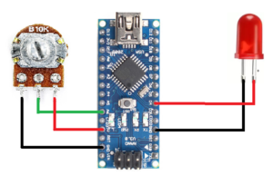
Here I just Interface the Potentiometer With Arduino Nano, when you rotate the potentiometer clockwise OR anticlockwise the LED will glow the potentiometer Value.
Circuit diagram
See In the circuit diagram potentiometer will connected to the Analog Pin (A0) And the LED will be Connected To the Digital Pin (D4).
|
1 2 3 4 5 6 7 8 9 10 11 12 13 14 15 16 17 18 19 20 21 22 23 |
//Prateek //www.justdoelectronics.com int LED_PIN = 4; void setup() { Serial.begin(9600); pinMode(LED_PIN, OUTPUT); } void loop() { int analogValue = analogRead(A0); int brightness = map(analogValue, 0, 1023, 0, 255); analogWrite(LED_PIN, brightness); Serial.print("Analog: "); Serial.print(analogValue); Serial.print("_Brightness: "); Serial.println(brightness); delay(100); } |
|
1 2 3 4 5 6 7 8 9 10 11 12 13 14 15 16 17 18 19 20 21 22 23 24 |
#define POTENTIOMETER_PIN A0 #define BUZZER 5 void setup() { // Set pin A0 as input pinMode(POTENTIOMETER_PIN, INPUT); // Set pin D5 as output pinMode(BUZZER, OUTPUT); } void loop() { // Read the value of the rotary potentiometer int potentiometerValue = analogRead(POTENTIOMETER_PIN); // Map the potentiometer value to a frequency int frequency = map(potentiometerValue, 0, 1023, 100, 1000); // Set the buzzer frequency tone(BUZZER, frequency); // Delay for 100 milliseconds delay(100); } |
4. LDR interfacing With Arduino Nano
|
1 2 3 4 5 6 7 8 9 10 11 12 13 14 15 16 17 18 19 20 21 22 23 24 25 26 27 28 29 30 |
#define LDR_PIN A1 #define LED_PIN 13 int ldrValue; // To store the value of the LDR int threshold = 500; // The threshold value for turning the LED on and off void setup() { // Set pin A1 as input pinMode(LDR_PIN, INPUT); // Set pin D13 as output pinMode(LED_PIN, OUTPUT); } void loop() { // Read the value of the LDR ldrValue = analogRead(LDR_PIN); // Check if the LDR value is less than the threshold if (ldrValue < threshold) { // Turn the LED on digitalWrite(LED_PIN, HIGH); } else { // Turn the LED off digitalWrite(LED_PIN, LOW); } // Delay for 100 milliseconds delay(100); } |
5.LM35 Sensor Interfacing with Arduino Nano
|
1 2 3 4 5 6 7 8 9 10 11 12 13 14 15 16 17 |
const int lm35_pin = A2; /* LM35 O/P pin */ void setup() { Serial.begin(9600); } void loop() { int temp_adc_val; float temp_val; temp_adc_val = analogRead(lm35_pin); /* Read Temperature */ temp_val = (temp_adc_val * 4.88); /* Convert adc value to equivalent voltage */ temp_val = (temp_val/10); /* LM35 gives output of 10mv/°C */ Serial.print("Temperature = "); Serial.print(temp_val); Serial.print(" Degree Celsius\n"); delay(1000); } |
6. RGB LED Interfacing With Arduino
|
1 2 3 4 5 6 7 8 9 10 11 12 13 14 15 16 17 18 19 20 21 22 23 24 25 26 27 28 29 30 31 32 33 34 35 36 37 38 39 40 41 42 43 44 |
#define RED 9 #define GREEN 10 #define BLUE 11 void setup() { // Set pins D9, D10, and D11 as output (Based on kit specs) pinMode(RED, OUTPUT); pinMode(GREEN, OUTPUT); pinMode(BLUE, OUTPUT); } void loop() { // Set the RGB LED to red digitalWrite(RED, HIGH); digitalWrite(GREEN, LOW); digitalWrite(BLUE, LOW); // Delay for 1 second delay(1000); // Set the RGB LED to green digitalWrite(RED, LOW); digitalWrite(GREEN, HIGH); digitalWrite(BLUE, LOW); // Delay for 1 second delay(1000); // Set the RGB LED to blue digitalWrite(RED, LOW); digitalWrite(GREEN, LOW); digitalWrite(BLUE, HIGH); // Delay for 1 second delay(1000); // Turn off the RGB LED digitalWrite(RED, LOW); digitalWrite(GREEN, LOW); digitalWrite(BLUE, LOW); // Delay for 1 second delay(1000); } |
7.DHT11 Sensor With Arduino
|
1 2 3 4 5 6 7 8 9 10 11 12 13 14 15 16 17 18 19 20 21 22 23 24 25 26 27 28 29 30 31 32 33 34 |
/* Example for Embedded DHT11 Sensor in 9-in-1 Expansion Board for Arduino Uno. By: RoboticX Team */ #include <DHT.h> #define DHTPIN 4 // Digital pin D4 connected to the DHT sensor DHT dht(DHTPIN, DHT11); // Initialize DHT sensor void setup() { // Set up serial communication Serial.begin(9600); // Initialize DHT sensor dht.begin(); } void loop() { // Read temperature and humidity float temperature = dht.readTemperature(); float humidity = dht.readHumidity(); // Print temperature and humidity to serial monitor Serial.print("Temperature: "); Serial.print(temperature); Serial.print("°C"); Serial.print(" Humidity: "); Serial.print(humidity); Serial.println("%"); // Delay for 2 seconds delay(2000); } |
8.16×2 Lcd interfacing With Arduino Nano
Here, I just connected the 16×2 LCD with Arduino nano Board.
|
1 2 3 4 5 6 7 8 9 10 11 12 13 14 15 16 17 18 19 |
//Prateek //www.justdoelectronics.com #include <LiquidCrystal.h> const int RS = 12, EN = 11, D4 = 10, D5 = 9, D6 = 8, D7 = 7; LiquidCrystal lcd(RS, EN, D4, D5, D6, D7); void setup() { lcd.begin(16, 2); lcd.setCursor(0, 0); lcd.print("Welcome To"); lcd.setCursor(2, 1); lcd.print("justdoelectronic"); } void loop() { } |
9. Ultrasonic Sensor Interfacing with Arduino Nano
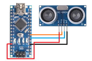
Here, I just connected to the Ultrasonic Sensor with Arduino Nano microcontroller

Circuit Diagram
|
1 2 3 4 5 6 7 8 9 10 11 12 13 14 15 16 17 18 19 20 21 22 23 24 25 26 27 28 |
//Prateek //www.justdoelectronics.com int trigPin = 4; int echoPin = 3; float duration_us, distance_cm; void setup() { Serial.begin(9600); pinMode(trigPin, OUTPUT); pinMode(echoPin, INPUT); } void loop() { digitalWrite(trigPin, HIGH); delayMicroseconds(10); digitalWrite(trigPin, LOW); duration_us = pulseIn(echoPin, HIGH); distance_cm = 0.017 * duration_us; Serial.print("distance: "); Serial.print(distance_cm); Serial.println(" cm"); delay(400); } |
THANKS

