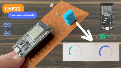
Getting Started with the ESP32 Board
step by step guide how the ESP32 board work
Introduction
In This Tutorial I will Explain All Details Related To The ESP32 Board, I will Show You How to Getting Started With ESP32 Board And How To Program The ESP32 Board Using Arduino IDE.
In Most Of the Industrial projects, they Used ESP32 Board Because of IoT applications that Require Low Power consumption.
Esp32 Providing Multiple Analog Pin With compared to Esp8266 And is also Supported by The MicroPythone Code.
Why ESP32?
In ESP32 Board Is Integrated with Wi-Fi And Dual-Core, Low Power Bluetooth, Low Power Consumption, and High performance.
ESP32 Is Small Size Board And Is Soo many Pin Available To Connect to the input and output Devices.
Compare To the Esp8266 Board Is Soo Many Analog pins Available On ESP32 Board and it Takes Low Power.
ESP32 Features
- Memory: 520Kb SRAM
- WiFi: 802.11/g/n/e/i
- Bluetooth: v4.2 BR/EDR And BLE
- CPU: Xtensa Dual-core(or Single-core) 32-bit LX6 Microprocessor, Operating at 160 or 240 MHz And Performing at up to 600 DMIPS
- 10 × touch sensors
- Hall sensor
- LED PWM up to 16 channels
- Ultra-low Power (ULP) Co-Processor
- 12-Bit SAR ADC up to 18 channels
- 2×8-bit DAC’s
- 4x SPI
- 2xI2S Interfaces
- 2xI2C Interfaces
- 3xUART
- Low Power Mode
-
34 × programmable GPIOs
Esp32 Pinout
Small Board
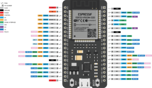
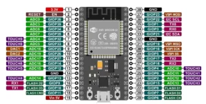
Let’s See the Esp32 Pin Diagram. I will show the Image of the Esp32 Board. If You are Interested In the read Data Sheet Just Download it Here.
GPIO Ports – GPIO Pins for General Purpose Input/Output, Multiple Pin Available to connect To the Digital And Analog Sensor.
Touch Ports – These Pins Work As Capacitive Sensors.
ADC – The ADCs (Analog TO Digital Converter) Have a Total of 16 Pins Available On the ESP32 Board.
Internal Memory
ESP32’s internal memory includes:
- 448 KB of ROM for booting and core functions
- 520 KB of on-chip SRAM for data and instructions
- 8 KB of SRAM in RTC, which is called RTC FAST Memory and can be used for data storage; it is accessed by the main CPU during RTC Boot from the Deep-sleep mode.
- 8 KB of SRAM in RTC, which is called RTC SLOW Memory and can be accessed by the ULP coprocessor during the Deep-sleep mode.
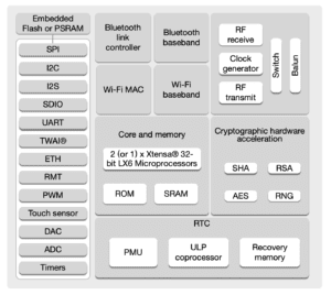
Here is the Block Diagram of the ESP32 Board
How To Program ESP32?
The ESP32 Board Is supported The C++ and Micro Python Code And you do This Programing With the Help Of Arduino IDE And Thonny IDE Software.
If you Want To Download The Software
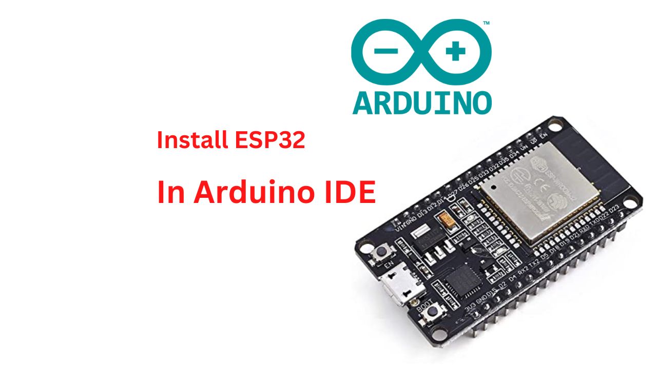
Esp32 With Arduino IDE
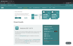
Let’s See How To Programing The ESP32 Board In Arduino IDE Software. First You are required To download the Arduino IDE Software And Install It In Your System.
Once The Arduino IDE is installed, Open it And Go To > Preferences. In the “Additional Board Manager URLs” Field, Just Copy the URL: And Paste it
|
1 |
https://raw.githubusercontent.com/espressif/arduino-esp32/gh-pages/package_esp32_index.json |
- Click “ok” To close the preferences Window.
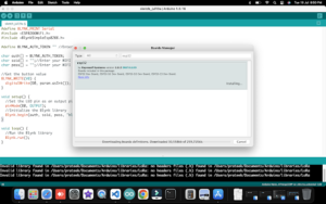
- Next, You Will Need To use the new access to actually add the ESP32 Boards to Your Arduino IDE. Just See The Image And Doo This Same Process
Is Soo That So Many Versions You Just Select One and Download It?
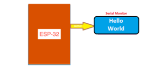
Hello World!
- Just Open the Arduino IDE Software And Type The Code
|
1 2 3 4 5 6 7 8 9 10 11 12 13 14 |
//Prateek //www.prateks.in //https://www.youtube.com/c/JustDoElectronics void setup() { // put your setup code here. Serial.begin(115200); Serial.println("Hello World!"); } void loop() { // put your main code here. } |
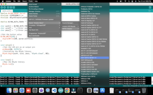
- And the Next Step You Just to Select The Proper Board And Click The Uploading Button
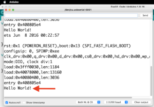
- When Code Will Uploaded Then Just Open the Serail Monitor And Press The Reset Button You See The “Hello World” Will Be Print
- I Hope You Understand How You are programming the ESP32 Board With Arduino IDE Software.
If You Like The Tutorial Then Plz Comment Below If you have Any Problem then You Ask In the Comment Section I will Try To Solve The Problem.
ESP32 With LED
Code
|
1 2 3 4 5 6 7 8 9 10 |
void setup() { pinMode(2, OUTPUT); } void loop() { digitalWrite(2, HIGH); delay(500); digitalWrite(2, LOW); delay(500); } |
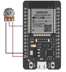
ESP32 With 10K PoT
Code
|
1 2 3 4 5 6 7 8 9 10 11 12 13 14 15 16 17 18 19 20 |
#define POTENTIOMETER_PIN 32 #define LED_PIN 21 void setup() { Serial.begin(9600); pinMode(LED_PIN, OUTPUT); } void loop() { int analogValue = analogRead(POTENTIOMETER_PIN); int brightness = map(analogValue, 0, 4095, 0, 255); analogWrite(LED_PIN, brightness); Serial.print("Analog value = "); Serial.print(analogValue); Serial.print(" => brightness = "); Serial.println(brightness); delay(100); } |
ESP32 Related Projects
