Solar Voltage Tracker Using Arduino
step by step guide voltage monitoring system using arduino
Introduction
in this article, we measure the solar power monitoring system using Arduino. we measured the parameters like solar panel voltage, Temperature, and Light intensity. Here we also discuss all the components which one we used in this project.
In This circuit, we measure all parameters in analog form we need to first convert into digital format and we take reading in the serial monitor and 16×2 LCD Display.
Components
The list of components we used in this project.
S.N | Components | Quantity |
1 | Arduino Nano | 1 |
2 | 16x2 LCD Display | 1 |
3 | LM35 Sensor | 1 |
4 | Voltage Sensor | 1 |
5 | LDR Sensor | 1 |
6 | 10k,(pot-10k) | 1 |
7 | Zero PCB | 1 |
Circuit Diagram
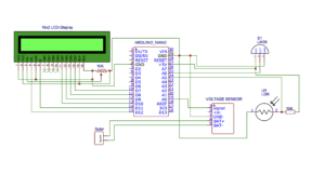
16×2 LCD is connected to the Arduino Nano
- LCD RS pin: Connected to digital pin 12 of the Arduino Nano.
- LCD Enable pin: Connected to digital pin 11 of the Arduino Nano.
- D4, D5, D6, and D7 pins are Connected to the 10, 9, 8, and 7 digital pins of the Arduino Nano.
LM35 Sensor measures temperature in degrees Celsius.
- It is connected to the Arduino Nano analog pin A6 to read the temperature values.
- The LM35 provides an analog voltage output proportional to the temperature.
The voltage is then calculated using a voltage divider circuit with resistors R1 and R2.
- R1: This resistor is connected between the voltage sensor output and the ground.
- R2: This resistor is connected between the voltage sensor output and the analog pin A0 of the Arduino.
Voltage = (Analog value/resistor factor) * Reference Voltage
Analog Value= Analog Output of Voltage Divider
Resistor factor= 1023.0/(R2/R1+R2)
Reference Volatge= 5V
Take resistor value
R1= 10k
R2= 1k
- Resistor factor= 1023.0 * (1000/1000+1000)
- resistor factor= 1023.0 * 0.5
- resistor factor= 511.5 for up to 10 v
Temperature Sensor = Analog Value * (5.0/1023.0)*100
The LDR Sensor is used to measure the ambient light intensity.
- It is connected to the Arduino Nano analog pin A5.
- The LDR Sensor resistance changes with the amount of light falling on it, and this change is used to calculate the light intensity.
RL= 500/Lux
The output voltage of this circuit can be calculated
- Vout= 5 * RL / (RL+3.3)
- RL is Load Resistance
Lux Formula = (2500 / Vout – 500) / 3.3
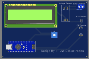
PCB Design
Code
|
1 2 3 4 5 6 7 8 9 10 11 12 13 14 15 16 17 18 19 20 21 22 23 24 25 26 27 28 29 30 31 32 33 34 35 36 37 38 39 40 41 42 43 44 45 46 47 48 49 50 51 52 53 54 55 56 57 58 59 60 61 62 |
#include <LiquidCrystal.h> #include <SoftwareSerial.h> LiquidCrystal lcd(12, 11, 10, 9, 8, 7); const int lm35_pin = A6; const int voltageSensor = A0; float vOUT = 0.0; float vIN = 0.0; float R1 = 30000.0; float R2 = 7500.0; int value = 0; float RLDR; float Vout; float Lux; void setup() { Serial.begin(9600); lcd.begin(16, 2); Serial.begin(9600); lcd.setCursor(0, 0); lcd.print(" Soler Energy "); lcd.setCursor(0, 1); lcd.print(" Measurement "); delay(2000); lcd.clear(); } void loop() { int temp_adc_val; float temp_val; temp_adc_val = analogRead(lm35_pin); temp_val = (temp_adc_val * 2.88); temp_val = (temp_val / 10); lcd.setCursor(0, 0); lcd.print("T:"); lcd.print(temp_val); Serial.print("Temperature = "); Serial.print(temp_val); Serial.print(" Degree Celsius\n"); value = analogRead(voltageSensor); vOUT = (value * 5.0) / 1024.0; vIN = vOUT / (R2 / (R1 + R2)); lcd.setCursor(0, 1); lcd.print("Solar Volt:"); lcd.setCursor(12, 1); lcd.print(vIN); int sensorValue = analogRead(A5); Vout = (sensorValue * 0.0048828125); RLDR = (10000.0 * (5 - Vout)) / Vout; Lux = (RLDR / 500); lcd.setCursor(10, 0); lcd.print("L:"); lcd.print(Lux); delay(1000); } |
Project Working
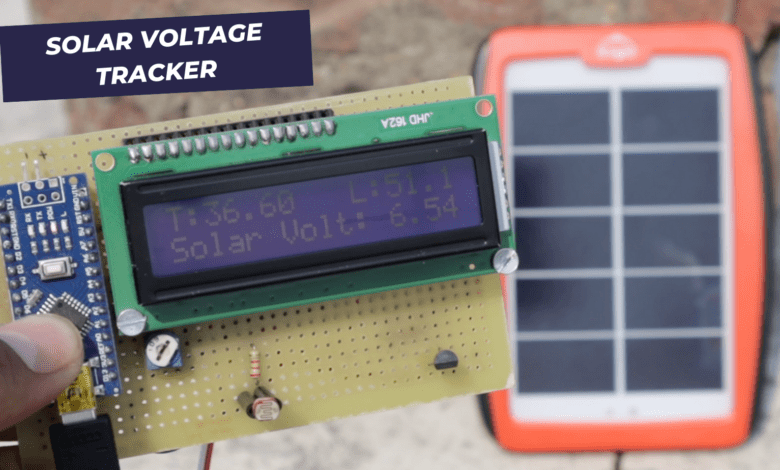
Here we show the solar panel voltage is 16×2 LCD Display and the solar panel is small that’s why it shows the voltage of 6.13v Only.
Now we connected to the LM35 Sensor And LDR and then you show all reading in the 16×2 LCD Display.
Video
Conclusion
In this project find out the solar Voltage, Temperature and light Intensity in future we make various projects related to the solar panel.
More Arduino Based Projects
