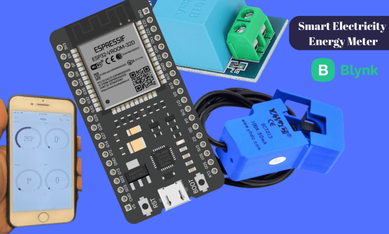
Smart Electricity Energy Meter With ESP32 & Blynk 2.0
IoT Based Smart Electricity Meter
Introduction
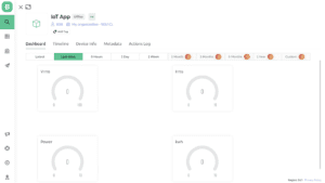
In this project, we build an IoT-based Smart Energy meter Using ESP32 Board and a new Blynk 2.0 application. we have ready many projects like Home Automation and DHT22 Sensor related to the Blynk application.
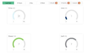
in this smart energy meter project we measure the AC Voltage, Current, and Watt, and Display The All Date to 16×2 LCD Display as well Blynk App.
Bill of Materials
S.N | Component's | Quantity |
1 | ESP32 Board | 1 |
2 | 16x2 LCD Display | 1 |
3 | AC Voltage Sensor (ZMPT101B) | 1 |
4 | Current Sensor (SCT-013-030,30A Non -invasive) | 1 |
5 | Capcitor 10uf | 1 |
6 | Resister 100ohm,10K | 1 |
7 | Breadboard | 1 |
AC Single Phase Voltage Sensor (ZMPT101B)
The ZMPT101B is an AC single-phase voltage sensor built in a micro voltage transformer. and is compatible with all devices like Arduino, ESP8266, ESP32 And Rpi.
The Voltage sensor is capable of measuring AC voltage range from 110v to 250v and also offers adjustable analog output. the potentiometer for adjusting and calibrating the ADC Output.
Specifications
- Voltage Range:- 250 volts
- Operating Temperature :- 40c to 70c
- Input Supply Voltage:- 5V
- small size and lightweight
- on-board op-amp circuit
Current sensor (SCT-013)
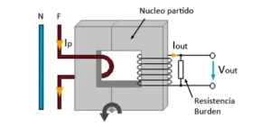
this type of current sensor is a non-invasive and split-core clamp meter sensor and they are commonly used to find the current value of an AC Transformer and are used for measuring alternating current in a building or company.
The SCT-013 is convenient to use, as it can be easily attached to the phase wire of high voltage.
This SCT-013 sensor has a primary winding, magnetic core, and secondary winding, which is composed of many truns of fine wire enclosed in the transformer.
Specifications
- Output Signal:- DC 0-1 V
- Input Signal:- 0-30A Ac
- Work Temperature :- -25c to 70c
- Resistance Grade:- Grade B
- Turn Ratio:- 1800:1
- Non-linearity:- 2-3%
- Build-in Sampling resistance:- 63 ohm
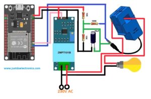
Circuit Diagram
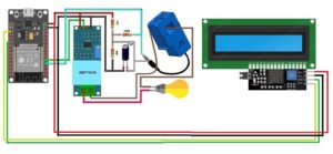
With 16×2 LCD Display (I2C)
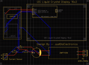
PCB Design
We Used the EasyEDA Software To Design A Proper PCB Board.
Setting Up Blynk 2.0 App
First We Sign up for The Blynk App
- Log in to the page then create the dashboard copy the AUTH TOKEN Number and paste in the Arduino Code.
Required Library
- EmonLib Library
EmonLib is a Continuous Monitoring of Electricity Energy repeats, every 5 or 10s, a sequence of voltage and current measurements.is automatic update.
Download Link EmonLib Library
- Blynk Library
Blynk is the most popular Internet of Things platform for connecting any hardware to the cloud, is suppoted all micro controller like arduino ESP8266, ESP32 etc.
Download Link Blynk Library
ZMPT101B Voltage Calibration
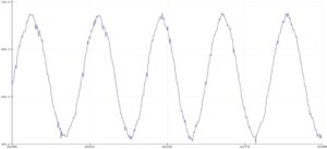
we first upload the small code to ESP32 board and calibrate the ZMPT101B Voltage Sensor & Measure The AC Voltage In Serial Plotter.
Now upload the following code to the Arduino Board.
|
1 2 3 4 5 6 7 8 9 10 |
void setup() { Serial.begin(9600); } void loop() { Serial.println(analogRead(A0)); delay(100); } |
After uploading the code, open the Serial Plotter.
Source Code
|
1 2 3 4 5 6 7 8 9 10 11 12 13 14 15 16 17 18 19 20 21 22 23 24 25 26 27 28 29 30 31 32 33 34 35 36 37 38 39 40 41 42 43 44 45 46 47 48 49 50 51 52 53 54 55 56 57 58 59 60 61 62 63 64 65 66 67 68 69 70 71 72 73 74 75 76 77 78 79 80 81 82 83 84 85 86 87 88 89 90 91 92 93 94 95 96 97 |
#include <LiquidCrystal_I2C.h> #define BLYNK_PRINT Serial #include "EmonLib.h" #include <WiFi.h> #include <WiFiClient.h> #include <BlynkSimpleEsp32.h> LiquidCrystal_I2C lcd(0x27, 16, 2); EnergyMonitor emon; #define vCalibration 83.3 #define currCalibration 0.50 BlynkTimer timer; char auth[] = "uhsuuwugweiiuwdbasduwqgdiuawq"; char ssid[] = "justdoelectronics"; char pass[] = "123456789"; float kWh = 0; unsigned long lastmillis = millis(); void myTimerEvent() { emon.calcVI(20, 2000); kWh = kWh + emon.apparentPower * (millis() - lastmillis) / 3600000000.0; yield(); Serial.print("Vrms: "); Serial.print(emon.Vrms, 2); Serial.print("V"); Serial.print("\tIrms: "); Serial.print(emon.Irms, 4); Serial.print("A"); Serial.print("\tPower: "); Serial.print(emon.apparentPower, 4); Serial.print("W"); Serial.print("\tkWh: "); Serial.print(kWh, 5); Serial.println("kWh"); lcd.clear(); lcd.setCursor(0, 0); lcd.print("Vrms:"); lcd.print(emon.Vrms, 2); lcd.print("V"); lcd.setCursor(0, 1); lcd.print("Irms:"); lcd.print(emon.Irms, 4); lcd.print("A"); delay(2500); lcd.clear(); lcd.setCursor(0, 0); lcd.print("Power:"); lcd.print(emon.apparentPower, 4); lcd.print("W"); lcd.setCursor(0, 1); lcd.print("kWh:"); lcd.print(kWh, 4); lcd.print("W"); delay(2500); lastmillis = millis(); Blynk.virtualWrite(V2, emon.Vrms); Blynk.virtualWrite(V3, emon.Irms); Blynk.virtualWrite(V4, emon.apparentPower); Blynk.virtualWrite(V5, kWh); } void setup() { Serial.begin(9600); Blynk.begin(auth, ssid, pass); lcd.begin(16, 2); emon.voltage(35, vCalibration, 1.7); // Voltage: input pin, calibration, phase_shift emon.current(34, currCalibration); // Current: input pin, calibration. timer.setInterval(5000L, myTimerEvent); lcd.setCursor(3, 0); lcd.print("IoT Energy"); lcd.setCursor(5, 1); lcd.print("Meter"); delay(3000); lcd.clear(); } void loop() { Blynk.run(); timer.run(); } |
Testing Photo
Here we connected the voltage sensor and current sensor with the AC Source.
Now is test time, the ESP32 Board is connected to the Wi-Fi network and Blynk app. The 16×2 LCD display will light up with all readings.
It displays the Vrms value and Irms Value, when the load is connected it changes the reading and displays the load value.
After a few seconds the display the Power and kwh value in the display as well new Blynk app and if the wifi network is not connected that’s time the LCD will display the correct reading only.
Video
Conclusion
In conclusion, the smart energy meter is a good example of a revolution in the monitoring of electricity consumption. the matter will save time and money.
we will enjoy the implementation and I hope you also love the article plz share it with your all friends.

