Home automation using arduino and bluetooth
Bluetooth Controlled Home Automation System
Introduction
In this article, I will explain how you used blutooth module and do your own Home Automation Project. Home Automation is a very Popular Project Topic if you are in college then it is the best mini-project for you.
In this project, I used the blutooth module(HC-05) And with the help of an Android mobile application, we controlled the AC fan And AC Light.
Bill of materials
S.N | Component | Quantity |
1 | Arduino Nano | 1 |
2 | HC-05 Bluetooth module | 1 |
3 | 4 Channel Relay Module | 1 |
4 | DC FAn | 1 |
5 | Red LED | 1 |
6 | Green LED | 1 |
7 | Blue LED | 1 |
8 | Zero PCB | 1 |
9 | DC Female Jack | 1 |
Component’s
Arduino Nano
- The Arduino Nano is the open-source smallest Embedded Development board based on Atmega328 SMD Package Microcontroller.
- Arduino Nano is a low-cost microcontroller and has many GPIO Pin available.
4-Channel Relay Module
- It is a 4-channel isolated 5V 10A Relay Module, A wide range of microcontrollers such as Arduino, AVR, PIC, ARM and so on can control it.
Features
- One normally closed contact and one normally open contact
- Channel: 4 channel Relay
- Operating Voltage: 3.3V to 5V
- High-impedance controller pin
HC-05 Bluetooth Module
The most demanding and popular due to its low price and extremely high features.
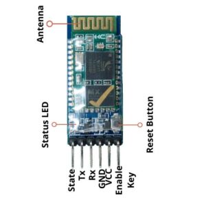
Features
- Bluetooth serial port Profile
- Protocol: UART
- Frequency: 2.4GHz ISM band
- Modulation: GFSK(Gaussian Frequency Shift Keying)
- Asynchronous Speed: 2.1Mbps(Max) / 160 kbps
- Synchronous Speed: 1Mbps/1Mbps
- Power supply: +3.3VDC 50mA
Circuit Diagram
Here I designed the block diagram of the Bluetooth Controlled Home Automation System On the input side we connected the blutooth module and output side we connected to the LED and DC Fan.
- The Blutooth Module is conected to the Pin Numbers D2 And D3 with an Arduino nano microcontroller.VCC Conected to the 5v & GND conected to the GND.
- We Used the 4-channel relay module which is a total of 6 Pin. As VCC conected to the 5v, GND Conected to the GND, and we used four digital Pin D4, D5, D6, and D7.
Code
|
1 2 3 4 5 6 7 8 9 10 11 12 13 14 15 16 17 18 19 20 21 22 23 24 25 26 27 28 29 30 31 32 33 34 35 36 37 38 39 40 41 42 43 44 45 46 47 48 49 50 51 52 53 54 55 56 57 58 59 60 61 62 63 64 65 66 67 68 69 70 71 72 73 74 75 76 77 78 79 80 81 82 83 84 85 86 87 88 89 90 91 92 93 94 95 96 97 98 99 100 101 102 103 104 105 106 107 108 109 |
#include <EEPROM.h> #include <SoftwareSerial.h> SoftwareSerial BT_Serial(2, 3); #define Relay1 4 #define Relay2 5 #define Relay3 6 #define Relay4 7 char bt_data; int load1, load2, load3, load4, power; void setup() { Serial.begin(9600); BT_Serial.begin(9600); pinMode(Relay1, OUTPUT); digitalWrite(Relay1, 1); pinMode(Relay2, OUTPUT); digitalWrite(Relay2, 1); pinMode(Relay3, OUTPUT); digitalWrite(Relay3, 1); pinMode(Relay4, OUTPUT); digitalWrite(Relay4, 1); load1 = EEPROM.read(1); load2 = EEPROM.read(2); load3 = EEPROM.read(3); load4 = EEPROM.read(4); power = EEPROM.read(5); delay(500); } void loop() { if (BT_Serial.available() > 0) { bt_data = BT_Serial.read(); } if (bt_data == 'A') { load1 = 0; EEPROM.write(1, load1); } if (bt_data == 'a') { load1 = 1; EEPROM.write(1, load1); } if (bt_data == 'B') { load2 = 0; EEPROM.write(2, load2); } if (bt_data == 'b') { load2 = 1; EEPROM.write(2, load2); } if (bt_data == 'C') { load3 = 0; EEPROM.write(3, load3); } if (bt_data == 'c') { load3 = 1; EEPROM.write(3, load3); } if (bt_data == 'D') { load4 = 0; EEPROM.write(4, load4); } if (bt_data == 'd') { load4 = 1; EEPROM.write(4, load4); } if (bt_data == 'E') { power = 0; EEPROM.write(5, power); } if (bt_data == 'e') { power = 1; EEPROM.write(5, power); } bt_data = '0'; if (power == 1) { digitalWrite(Relay1, 1); digitalWrite(Relay2, 1); digitalWrite(Relay3, 1); digitalWrite(Relay4, 1); } else { digitalWrite(Relay1, load1); digitalWrite(Relay2, load2); digitalWrite(Relay3, load3); digitalWrite(Relay4, load4); } BT_Serial.print(power); BT_Serial.print(";"); BT_Serial.print(load1); BT_Serial.print(";"); BT_Serial.print(load2); BT_Serial.print(";"); BT_Serial.print(load3); BT_Serial.print(";"); BT_Serial.print(load4); BT_Serial.println(";"); delay(500); } |
Android Mobile Application
Working Demo
Now first we connect the Blutooth module with the Android mobile app.
- First, we turn on the first light we just Touch the “ON Button” The LED will be ON.
- and if we Touch the “OFF Button” Then Led Will OFF.
- This time we used the voice command if I say “Light On” Then the LED will be ON And if I say “Light Off” then the Light Will be OFF.
- if we click the all on Button then at a time all LED and fan will be ON like if we click the all off button all devices will OFF
Video
Conclusion
Here we design a simple Bluetooth-based home automation project. it works perfectly but the control distance is less only 10 meters, if you want unlimited distance then you can make a IoT IoT-based home Automation.
Thanks for the time to read the article is helpful plz share it with your friends.
Arduino Project’s


