GSM Based Water Level Monitoring System Using Arduino
GSM Based Water Level Monitoring System Using Arduino
Overview of Project
In This Project, We Make a water level monitoring System using Arduino Nano microcontroller and Gsm-based.
Water Waste is a very common problem in our world. is Soo many homes fill the tank with the help of the water pump but sometimes the water pump fills the tank but is automatically not Motor to off that’s time water is overflow.
This project helps to indicate the water level of the tank suppose the motor fills the tank and the water is level with the tank that time the motor is automatically off, And the GSM Module Send the Full message to the owner your Water Tank is full.
In this Project, I used the Arduino Nano Microcontroller,16×2 Lcd Display, GSM Module, Float Sensor, Buzzer, LED, And Buzzer.
Bill Of Materials
The GSM-Based Water Level Monitoring System Requires the Following Components.
S.N. | Components | Quantity | Buy Link |
1 | Arduin nano | 1 | |
2 | 16x2 Lcd Display | 1 | |
3 | 10k port | 1 | |
4 | Lm2596 Voltage Convter | 1 | |
5 | Sim800l Gsm Module | 1 | |
6 | Float Sensor | 1 | |
7 | Green Led | 1 | |
8 | Red Led | 1 | |
9 | Buzzer | 1 |
Circuit Diagram
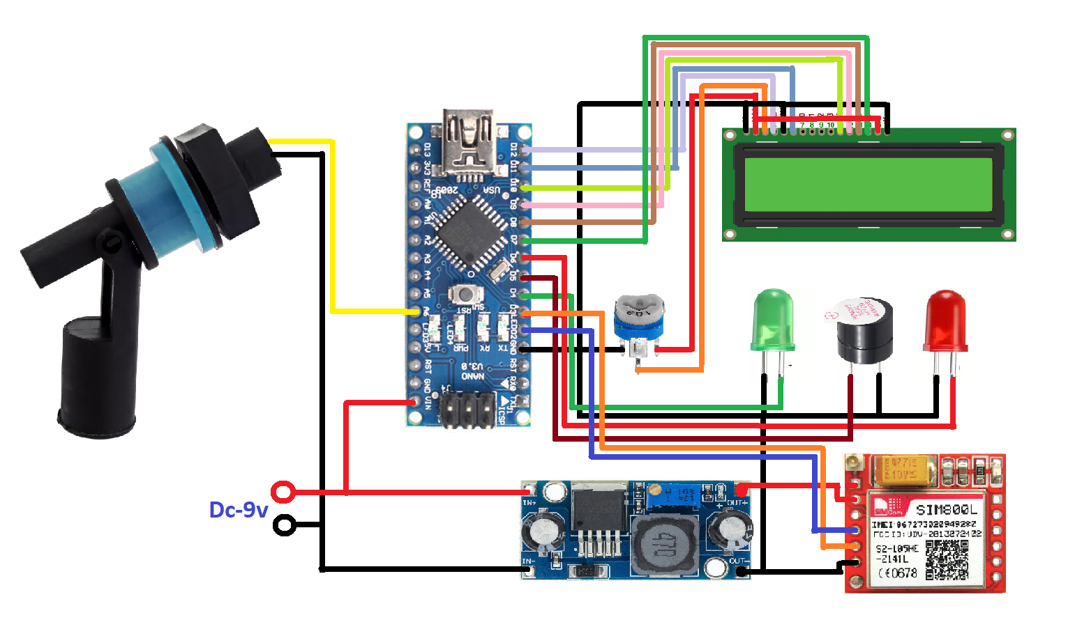
Here is the circuit of this Project, You Also See the Components Connected to This Project.

This project requires to 9v DC power Supply Is Impotent To this Project. We Used The Sim800l GSM Module And required The 3.7v DC supply, That’s why I Used The LM2596 Step-Down converter the Convert the 9v DC supply to the 3.7v DC supply. The Gsm Module is Connected to the PIN D2-Rx And D3-Tx.

16×2 LCD, they will show the water level of the tank Suppose the water level is empty then LCD Will Display the water level is empty and if the water level is Full they Display Ware Tank Level Is Full.the 16×2 Lcd Display Will Content To The Pin Number D12,D11,D10,D9,D8,D7 And Vcc To +5v ,GND TO GND.
These Are The Impotent Connection Of This Project And The Float Sensor Is an Electromagnetic Type Of Sensor Connected to PIN A1. led Will Content To The PIN D4 And D6 Buzzer Will Content to PIN D5.
Block Diagram

In This Block Diagram, I will Just Show The Input And Output Device The input Device Is a Float Sensor And the Output Device Is a 16×2 LCD, LEDs, a Buzzer, And a GSM Module.
Flow Chart

This Image Will Show The Total Working flow Of This Project means How The Project Will Work Step by Step.
First You Start the System I mean the Microcontroller and All Input and Output Devices will Activate and is ready to take action.
And The 16×2 Lcd Will Display The Welcome Text Message “Welcome To JustDoElectronics” Then Show That The Flow Sensor Conduction Like will be High Or Low.
Suppose the tank Is Empty then Is Float Sensor Will be Low Suppose The Motor Fill The Tank Float Sensor will be HIGH That’s the time GSM Sends a Text Message To a Particular Mobile Number. The Water Tank Is Full Plz Turn Of The Motor.
When You Understand The Flow Chart Of This Project Then I think Is clear In the Code Section.
Source Code
This Source Code Is written In Arduino IDE Software You Just Copy This Code And Paste it into the Arduino IDE Software Select the Arduino Nano Board And Upload It.
Before you upload you Just Change Your country code and Mobile Number here
|
1 |
sim800.println("AT+CMGS=\"+91xx30584864\"\r"); |
Now you just upload the Code In Arduino Nano Microcontroller
|
1 2 3 4 5 6 7 8 9 10 11 12 13 14 15 16 17 18 19 20 21 22 23 24 25 26 27 28 29 30 31 32 33 34 35 36 37 38 39 40 41 42 43 44 45 46 47 48 49 50 51 52 53 54 55 56 57 58 59 60 61 62 63 64 65 66 67 68 69 70 71 72 73 74 75 76 77 78 79 80 81 82 83 84 85 86 87 88 89 90 91 92 93 94 95 96 97 98 99 100 101 102 103 104 105 106 107 108 109 110 |
//Prateek //www.prateeks.in #include<LiquidCrystal.h> #include<Wire.h> #include <SoftwareSerial.h> #define rxPin 2 #define txPin 3 SoftwareSerial sim800(rxPin, txPin); LiquidCrystal lcd(12, 11, 10, 9, 8, 7); int FloatSensor = 15; int red = 6; int green = 4; int relay = 14; int buzzer = 5; int buttonState = 1; void setup() { Serial.begin(9600); sim800.begin(9600); sim800.println("AT"); pinMode(FloatSensor, INPUT_PULLUP); pinMode (red, OUTPUT); pinMode (relay, OUTPUT); pinMode (green, OUTPUT); pinMode (buzzer, OUTPUT); lcd.begin(16, 2); lcd.setCursor(0, 0); lcd.print(" Welcome To"); lcd.setCursor(0, 1); lcd.print(" Our Projects"); delay(3000); lcd.setCursor(0, 0); lcd.print("REPRESENTED BY:- "); lcd.setCursor(0, 1); lcd.print("JustDoElectronics"); delay(3000); lcd.clear(); } void loop() { buttonState = digitalRead(FloatSensor); if (buttonState == HIGH) { digitalWrite(red, LOW); digitalWrite(green, HIGH); digitalWrite(buzzer, LOW); digitalWrite(relay, LOW); Serial.println("WATER LEVEL - LOW"); lcd.setCursor(0, 0); lcd.print("W-Level:- Normal "); lcd.setCursor(0, 1); lcd.print(" Motor ON."); SendMessageTankNotFull(); } else { digitalWrite(red, HIGH); digitalWrite(green, LOW); digitalWrite(buzzer, HIGH); digitalWrite(relay, HIGH); Serial.println("WATER LEVEL - HIGH"); lcd.setCursor(0, 0); lcd.print("W-Level:- FULL.. "); lcd.setCursor(0, 1); lcd.print(" Motor OFF"); SendMessageTankFull();; } delay(1000); } void SendMessageTankFull() { sim800.println("AT+CMGF=1"); delay(1000); sim800.println((char)26); delay(100); sim800.println("AT+CMGS=\"+91xx30584864\"\r"); delay(1000); sim800.println("Water tank is full"); delay(1000); } void SendMessageTankNotFull() { sim800.println("AT+CMGF=1"); delay(1000); sim800.println((char)26); delay(100); sim800.println("AT+CMGS=\"+91xx30584864\"\r"); delay(1000); sim800.println("Monitoring started"); delay(1000); } |
Testing Of This Project
Now The Float Sensor Is Low And Is Sending The Text Message Water Level Is Empty.

Now This Time The Float Sensor Will be High And Is Sending an Alert Message to the Mobile Number Your Tank Will be Full.

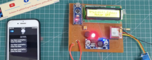
Check the Message
Video Tutorial

Hi
I wonder if you can assist I would like to build this project but cant find a 10k port
Can you give me more infomation?
Thanks
Richard