EM-18 RFID Interfacing With Arduino, ESP8266 & ESP32
EM-18 RFID Interfacing With ESP32
Introduction
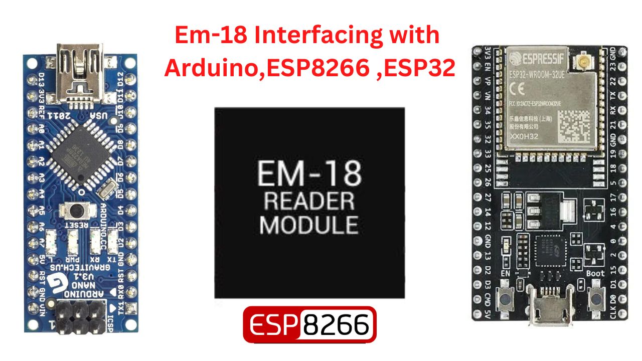
In this tutorial, we will Interface with the EM-18 RFID module using Arduino Nano, ESP8266, and ESP32 board.
Overview
EM18 work on Radio frequency identification RFID is a wireless identification technology that uses Radio wave to identify the present of RFID tags.
RFID is used in many applications like attendance systems in which every person will have a separate RFID tag which will help identify the person.
1. RFID Tag
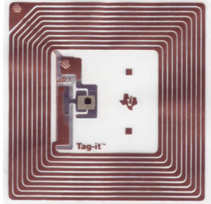
RFID tag includes a microchip with a radio antenna mounted on the tag and carries 12 Byte unique Identification Number.
2. RFID Reader
RFID Reader is used to reading the unique ID from the RFID tag whenever the RFID tag comes in range, RFID reader reads its unique ID and transmits it serially to the microcontroller.
Basically, RFID systems are categorized as active and passive based on how they are powered and there range.
1. Active RFID System
- Active RFID tags have their own transmitter and power source
- They operate at A55MHz, 245GHz
- They typically have a read range of feet to 300 feed.
2. Passive RFID System.
- Passive RFID tags do not have a transmitter, they simply reflect energy (radio waves).
- They operate in low-frequency (125 KHz) and high-frequency (13 MHz) bands.
How to RFID System Work.
RFID Reader has a transceiver which generates a radio signal and transmits it through the antenna.
The signal itself is in the form of energy which is used to activate and power the tag.
RFID reader puts this unique ID data in the form of bytes on serial Tx pins. This data can be used by the microcontroller serially using UART communication.
EM18 RFID Reader
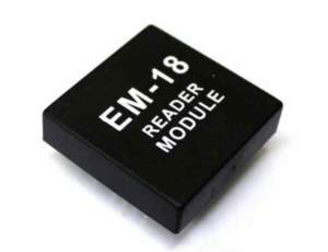
EM18 is an RFID Reader which is used to read RFID tags of frequency 125 KHz.
After reading the tags, it transmits the unique ID serially to the microcontroller using the UART communication.
Features
- Serial RS232/ output
- The operation frequency is 125KHz
- The range is 5-8m
Bill of Material
S.N | Component | Quantity | LINK To BUY |
1 | EM-RFID Module | 1 | |
2 | RFID Card | 1 | |
3 | Arduino Nano | 1 | |
4 | ESP8266 | 1 | |
5 | ESP32 | 1 |
Circuit Diagram
In this circuit diagram, we interface the EM-18 module with Arduino Nano Microcontroller. It required only 3 wires to connect the EM-18 module to the Arduino Nano board.
EM-18 Arduion Nano
- VCC – VCC
- GND – GND
- Tx – Rx
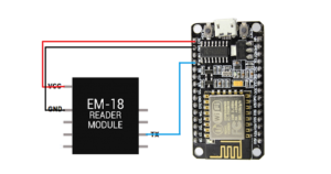
In this circuit Diagram, we interface the EM-18 module with ESP8266 Board. Are only 3 wires required to connect the EM-18 module?
EM-18 ESP8266
- VCC – VCC
- GND – GND
- Tx – Rx
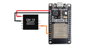
In this Circuit Diagram, we interfaced EM-18 modules with ESP32 Board. Are only 3 wires required to connect the EM-18 module?
EM-18 ESP32
- VCC – VCC
- GND – GND
- Tx – Rx
Just follow the Circuit carefully and select the proper Board and upload the code and we just scan the RFID tag Number.
Source Code
|
1 2 3 4 5 6 7 8 9 10 11 12 13 14 15 16 17 18 19 20 21 22 23 24 |
//Prateek //www.justdoelectronics.com int count = 0; char card_no[12]; void setup() { Serial.begin(9600); } void loop() { if(Serial.available()) { count = 0; while(Serial.available() && count < 12) { card_no[count] = Serial.read(); count++; delay(5); } Serial.print(card_no); } } |
- I hope you like the article if you like it share it with your friends and comment on it.
Video Tutorial
If you Interested in More ESP32 Projects
- Getting Started with the ESP32 Board
- IoT-Based Patient Health Monitoring System
- IoT Based Temperature Monitoring System
